

Question: The greatest common divisor or the highest common factor is the largest natural number that divides two numbers without leaving a remainder. Hope you
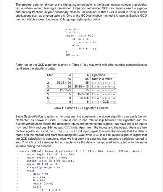
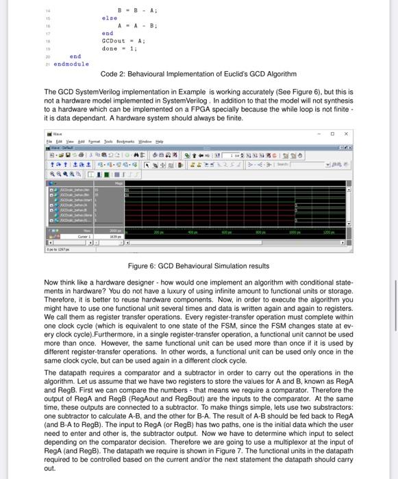
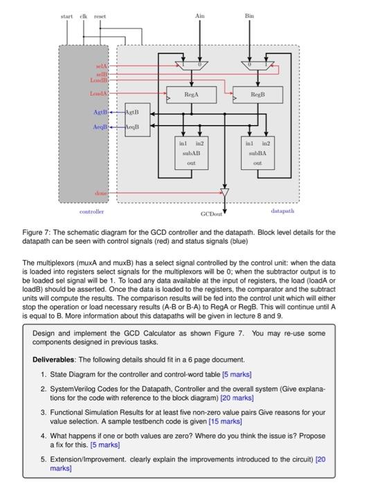
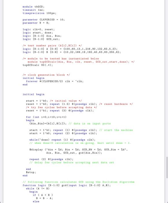
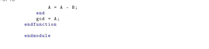
The greatest common divisor or the highest common factor is the largest natural number that divides two numbers without leaving a remainder. Hope you remember GCD calculations used in algebra and solving fractions in your secondary classes. In addition to that GCD is used in various other applications such as cryptography etc. One of the GCD estimation method is known as Euclid's GCD method, which is described using C language-style syntax below. 2 3 4 1 T W U Step 1. 2. 3. 4. 1 5. 6. 7. A dry-run for the GCD algorithm is given in Table 1. You may try it with other number combinations to familiarise the algorithm better. a = ain; b = bin: while (a } done = 0; A Ain; B Bin; while (A1-B) begin if (a > a 55 55-35 20 20 20-15-5 else if (AB) b) a a b; GCD-a: b) { Since SystemVerilog is quite rich in programming constructs the above algorithm can easily be im- plemented as shown in Code. There is one to one relationship between the algorithm and the SystemVerilog code except the additional inputs and some control signals. We have two 8-bit inputs (Ain and Bin) and one 8-bit output (GC Dout). Apart from the inputs and the output, there are two control signals start and done. The start is a 1-bit input signal to inform the module that the data is ready and the module can start calculating the GCD, while done is a 1-bit output signal to signal that the GCD calculation is complete. Also, we first copy the data into two temporary variables named A and B, which is not essential, but advisable since the data is manipulated and copied onto the same variable during the process. output logic [N-1:01 GCDout; logic [N-1:01 A, B; always (posedge start) begin b = b = a; b Operation 35 Data in a and b 35 abaca-b b>abb-a 15 abaca-b 35-2015 5 5 5 Table 1: Euclid's GCD Algorithm Example module GCDcalc_behav (parameter N 8 ) (Ain, Bin. start, GCDout, done); input logic [N-1:01 Ain. Bin; input logic start, done; 15-5-10 babe b-a 10-5-5 ba..b-b-a 5 a b GCD a 14 15 16 17 18 19 20 end endmodule tatt Da else Code 2: Behavioural Implementation of Euclid's GCD Algorithm The GCD SystemVerilog implementation in Example is working accurately (See Figure 6), but this is not a hardware model implemented in SystemVerilog. In addition to that the model will not synthesis to a hardware which can be implemented on a FPGA specially because the while loop is not finite- it is data dependant. A hardware system should always be finite. pouk B B A; Gainer A AB; You Ft Jooks Bookmarks Window end GCDout A: done = 1; 22 4-4-04-49 K 883 SHAK MARE Figure 6: GCD Behavioural Simulation results Now think like a hardware designer - how would one implement an algorithm with conditional state- ments in hardware? You do not have a luxury of using infinite amount to functional units or storage. Therefore, it is better to reuse hardware components. Now, in order to execute the algorithm you might have to use one functional unit several times and data is written again and again to registers. We call them as register transfer operations. Every register-transfer operation must complete within one clock cycle (which is equivalent to one state of the FSM, since the FSM changes state at ev- ery clock cycle). Furthermore, in a single register-transfer operation, a functional unit cannot be used more than once. However, the same functional unit can be used more than once if it is used by different register-transfer operations. In other words, a functional unit can be used only once in the same clock cycle, but can be used again in a different clock cycle. The datapath requires a comparator and a subtractor in order to carry out the operations in the algorithm. Let us assume that we have two registers to store the values for A and B, known as RegA and RegB. First we can compare the numbers that means we require a comparator. Therefore the output of RegA and RegB (RegAout and RegBout) are the inputs to the comparator. At the same time, these outputs are connected to a subtractor. To make things simple, lets use two substractors: one subtractor to calculate A-B, and the other for B-A. The result of A-B should be fed back to Rega (and B-A to RegB). The input to RegA (or RegB) has two paths, one is the initial data which the user need to enter and other is, the subtractor output. Now we have to determine which input to select depending on the comparator decision. Therefore we are going to use a multiplexor at the input of RegA (and RegB). The datapath we require is shown in Figure 7. The functional units in the datapath required to be controlled based on the current and/or the next statement the datapath should carry out. start elk reset selA sell LoadB LamA Agt Aegl controller AgtB Ang Ain RegA inl marks] in2 subAB out GCDout Bin RegB inl in2 subBA out datapath Figure 7: The schematic diagram for the GCD controller and the datapath. Block level details for the datapath can be seen with control signals (red) and status signals (blue) The multiplexors (muxA and muxB) has a select signal controlled by the control unit: when the data is loaded into registers select signals for the multiplexors will be 0; when the subtractor output is to be loaded sel signal will be 1. To load any data available at the input of registers, the load (loadA or loadB) should be asserted. Once the data is loaded to the registers, the comparator and the subtract units will compute the results. The comparison results will be fed into the control unit which will either stop the operation or load necessary results (A-B or B-A) to RegA or RegB. This will continue until A is equal to B. More information about this datapaths will be given in lecture 8 and 9. Design and implement the GCD Calculator as shown Figure 7. You may re-use some components designed in previous tasks. Deliverables: The following details should fit in a 6 page document. 1. State Diagram for the controller and control-word table [5 marks] 2. SystemVerilog Codes for the Datapath, Controller and the overall system (Give explana- tions for the code with reference to the block diagram) [20 marks] 3. Functional Simulation Results for at least five non-zero value pairs Give reasons for your value selection. A sample testbench code is given [15 marks] 4. What happens if one or both values are zero? Where do you think the issue is? Propose a fix for this. [5 marks] 5. Extension/Improvement. clearly explain the improvements introduced to the circuit) [20 module tbGCD; timeunit ins; timeprecision 100ps; parameter CLKPERIOD 10; parameter N = 8; logic clk-0, reset; logic start, done; logic [N-1:0] Ain, Bin; logic [N-1:0] GCD_out; /* test number paire (A[i];B[i]) / logic [N-1:01A [0:9] logic [N-1:0] B [0:9] /module to be tested has instantiated below module topGCDeale (Ain, Bin, clk, reset, GCD_out, start, done); / topGCDeale UO (..); / clock generation block / initial begin forever #(CLKPERIOD/2) clk = "clk; end initial begin start= 1'b0; / initial value / reset 1'b0; repeat (1.5) (100.60.13.1.216.90.132,83,5,0); (10,22,169,19,192,40,63,83,255,6); / try few cycles before accepting data reset 1'b1; repeat (3) @(posedge clk); for (int i=0; i
Step by Step Solution
3.42 Rating (149 Votes )
There are 3 Steps involved in it
Youre referring to the Greatest Common Divisor GCD of two numbers Yes Im familiar with it The GCD of ... View full answer

Get step-by-step solutions from verified subject matter experts