

Question: The input r(t) to a DSBSC receiver is a DSB signal s(t) = A m(t)cos (21fet) corrupted by additive white Gaussian noise with two-sided power
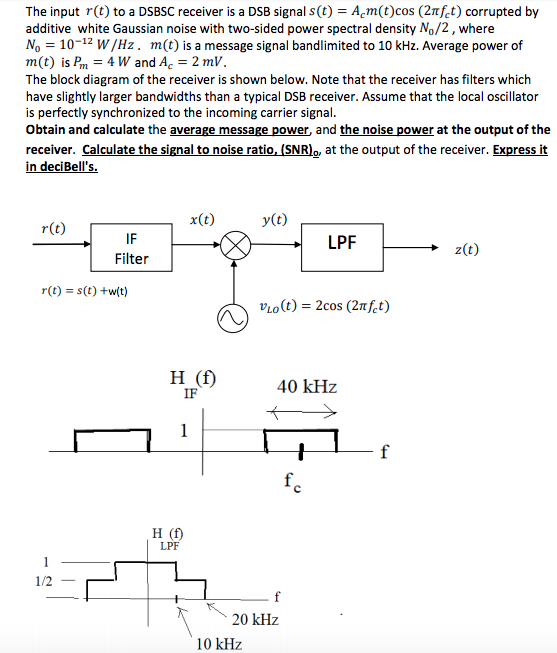
The input r(t) to a DSBSC receiver is a DSB signal s(t) = A m(t)cos (21fet) corrupted by additive white Gaussian noise with two-sided power spectral density N,/2, where No = 10-12 W/Hz, m(t) is a message signal bandlimited to 10 kHz. Average power of m(t) is Pm = 4 W and Ac = 2 mV. The block diagram of the receiver is shown below. Note that the receiver has filters which have slightly larger bandwidths than a typical DSB receiver. Assume that the local oscillator is perfectly synchronized to the incoming carrier signal. Obtain and calculate the average message power and the noise power at the output of the receiver. Calculate the signal to noise ratio, (SNR),, at the output of the receiver. Express it in deciBell's. x(t) y(t) r(t) IF Filter LPF z(t) r(t) = s(t) +w(t) VLO(t) = 2cos (2nfet) H (f) IF 40 kHz 1 + f fc H (f) LPF 1/2 20 kHz 10 kHz
Step by Step Solution
There are 3 Steps involved in it

Get step-by-step solutions from verified subject matter experts