

Question: The main objective is to slice apples: Description: A frame holds the mechanical parts of the slicing machine. Three double acting cylinders will activate the
The main objective is to slice apples:
Description:
A frame holds the mechanical parts of the slicing machine.
Three double acting cylinders will activate the slicing process in a sequential
motion.
The first cylinder is activated in a horizontal motion to provide the apple to the slicer
area from the storage.
The second cylinder is activated in a vertical motion for the slicing process.
The third cylinder is activated in a horizontal motion to drop the sliced apple in the
collecting package.
2 IR sensors are to be used (1 sensor is for detecting apples arrival in front of piston 1 and the other sensor is to detect tge apple arrival in from lf piston 2 to be cut
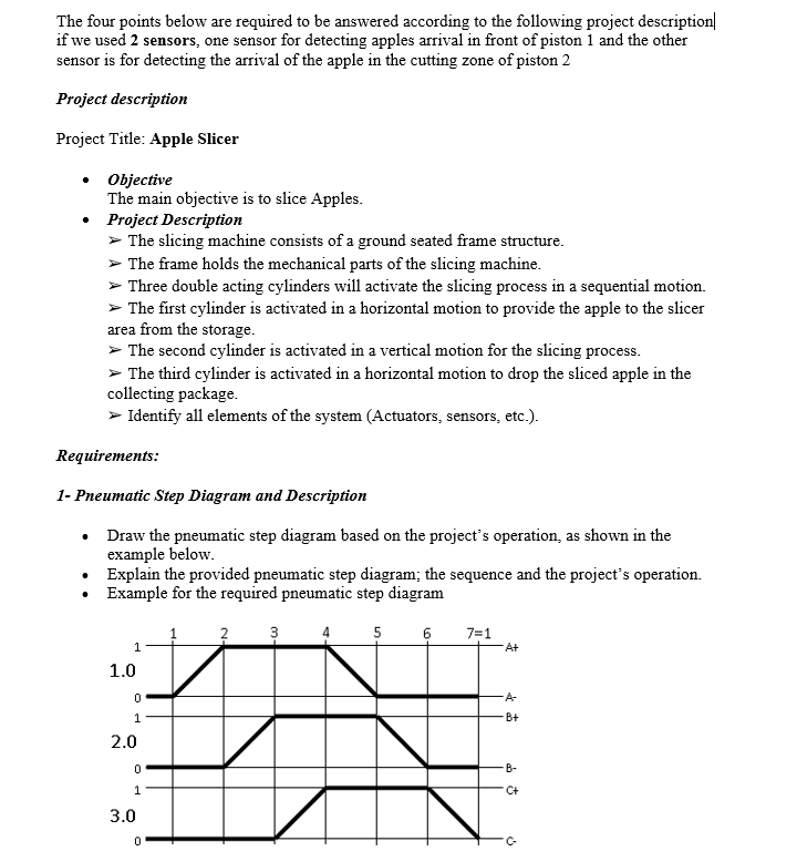
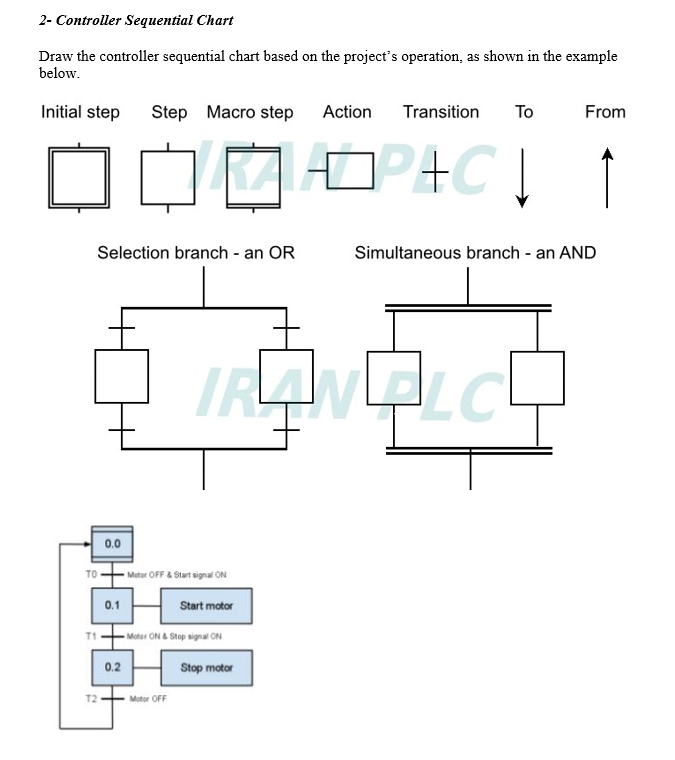
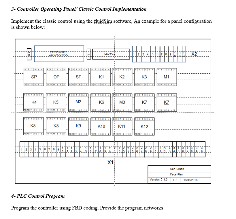
The four points below are required to be answered according to the following project description| if we used 2 sensors, one sensor for detecting apples arrival in front of piston 1 and the other sensor is for detecting the arrival of the apple in the cutting zone of piston 2 Project description Project Title: Apple Slicer Objective The main objective is to slice Apples. Project Description > The slicing machine consists of a ground seated frame structure. The frame holds the mechanical parts of the slicing machine. > Three double acting cylinders will activate the slicing process in a sequential motion. The first cylinder is activated in a horizontal motion to provide the apple to the slicer area from the storage. > The second cylinder is activated in a vertical motion for the slicing process. The third cylinder is activated in a horizontal motion to drop the sliced apple in the collecting package. > Identify all elements of the system (Actuators, sensors, etc.). Requirements: 1- Pneumatic Step Diagram and Description Draw the pneumatic step diagram based on the project's operation, as shown in the example below. Explain the provided pneumatic step diagram; the sequence and the project's operation. Example for the required pneumatic step diagram 3 5 6 7=1 A+ 1.0 0 1 B+ 2.0 0 F B- 1 C+ 3.0 0 C- 2- Controller Sequential Chart Draw the controller sequential chart based on the project's operation, as shown in the example below. Initial step Step Macro step Action Transition From ]] Selection branch - an OR Simultaneous branch - an AND TRY Qud 0.0 TOM OFF & Start signal ON 0.1 Start motor TI - Moto ON & Stop signat ON 0.2 Stop motor T2 Motor OFF 3- Controller Operating Panel Classic Control Implementation Implement the classic control using the fluidSim software, An example for a panel configuration is shown below: 8 - Power Supply 220VAC/24VDC LED PC 11121314 00 9 X2 7034 SP OP ST K1 K2 K3 M1 101011 10102 10101112 1010Gana 010 01012 100 none 90334 907534 539 D02634 K4 K5 M2 K6 M3 K7 K7 10 10 11 12 10 10 mona 10/02 100 g 1000 1000 10 10 GA K8 K8 K9 K10 K11 K12 101012 101 102 10.106.2 10 1011692 10/101692 1121314151617 1111 2.3.4.515.11.& X1 Can Crush Face Plan Version: 1.0 L.3 13/06/2018 4- PLC Control Program Program the controller using FBD coding. Provide the program networks The four points below are required to be answered according to the following project description| if we used 2 sensors, one sensor for detecting apples arrival in front of piston 1 and the other sensor is for detecting the arrival of the apple in the cutting zone of piston 2 Project description Project Title: Apple Slicer Objective The main objective is to slice Apples. Project Description > The slicing machine consists of a ground seated frame structure. The frame holds the mechanical parts of the slicing machine. > Three double acting cylinders will activate the slicing process in a sequential motion. The first cylinder is activated in a horizontal motion to provide the apple to the slicer area from the storage. > The second cylinder is activated in a vertical motion for the slicing process. The third cylinder is activated in a horizontal motion to drop the sliced apple in the collecting package. > Identify all elements of the system (Actuators, sensors, etc.). Requirements: 1- Pneumatic Step Diagram and Description Draw the pneumatic step diagram based on the project's operation, as shown in the example below. Explain the provided pneumatic step diagram; the sequence and the project's operation. Example for the required pneumatic step diagram 3 5 6 7=1 A+ 1.0 0 1 B+ 2.0 0 F B- 1 C+ 3.0 0 C- 2- Controller Sequential Chart Draw the controller sequential chart based on the project's operation, as shown in the example below. Initial step Step Macro step Action Transition From ]] Selection branch - an OR Simultaneous branch - an AND TRY Qud 0.0 TOM OFF & Start signal ON 0.1 Start motor TI - Moto ON & Stop signat ON 0.2 Stop motor T2 Motor OFF 3- Controller Operating Panel Classic Control Implementation Implement the classic control using the fluidSim software, An example for a panel configuration is shown below: 8 - Power Supply 220VAC/24VDC LED PC 11121314 00 9 X2 7034 SP OP ST K1 K2 K3 M1 101011 10102 10101112 1010Gana 010 01012 100 none 90334 907534 539 D02634 K4 K5 M2 K6 M3 K7 K7 10 10 11 12 10 10 mona 10/02 100 g 1000 1000 10 10 GA K8 K8 K9 K10 K11 K12 101012 101 102 10.106.2 10 1011692 10/101692 1121314151617 1111 2.3.4.515.11.& X1 Can Crush Face Plan Version: 1.0 L.3 13/06/2018 4- PLC Control Program Program the controller using FBD coding. Provide the program networks
Step by Step Solution
There are 3 Steps involved in it

Get step-by-step solutions from verified subject matter experts