

The mass M shown in FIGURE 5 is to be held in position by two hydraulic pistons
Question:
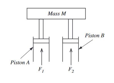
The mass M shown in FIGURE 5 is to be held in position by two hydraulic pistons (A and B) which exert forces F1 and F2 (respectively) onto the mass. The total for FT (where FT = F1 + F2) is to be controlled at a constant value.
The force F2 is uncontrolled, it is set at a nominal value however this may vary due to changes in the pressure of the hydraulic fluid supplying piston B.
A control loop is to be used to maintain the total applied force FT by controlling the magnitude of F1
(a) Draw a block diagram for a proportional control system (with bias) to control FT.
(b) Derive a relationship between the actual total force (FT) and:
• Force F2 • Bias B • Controller gain C • Desired value DV • Feedback gain G
(c) If the desired value (for FT) is 5 kN, F2 is set nominally to 3 kN and the controller and feedback gains are 1, determine a suitable value for the bias.
(d) If the desired value remains 5 kN, using the bias you calculated and the values set out in part
(c) determine the value of the offset produced if F2 increases to 4 kN
Expert Answer:


Core Concepts Of Accounting Information Systems
ISBN: 9780470507025
11th Edition
Authors: Nancy A. Bagranoff, Mark G. Simkin, Carolyn Strand Norman
