

Question: The member having a rectangular cross section, Fig. 6 - 2 8 a , is designed to resist a moment of 4 0 N *
The member having a rectangular cross section, Fig. a is
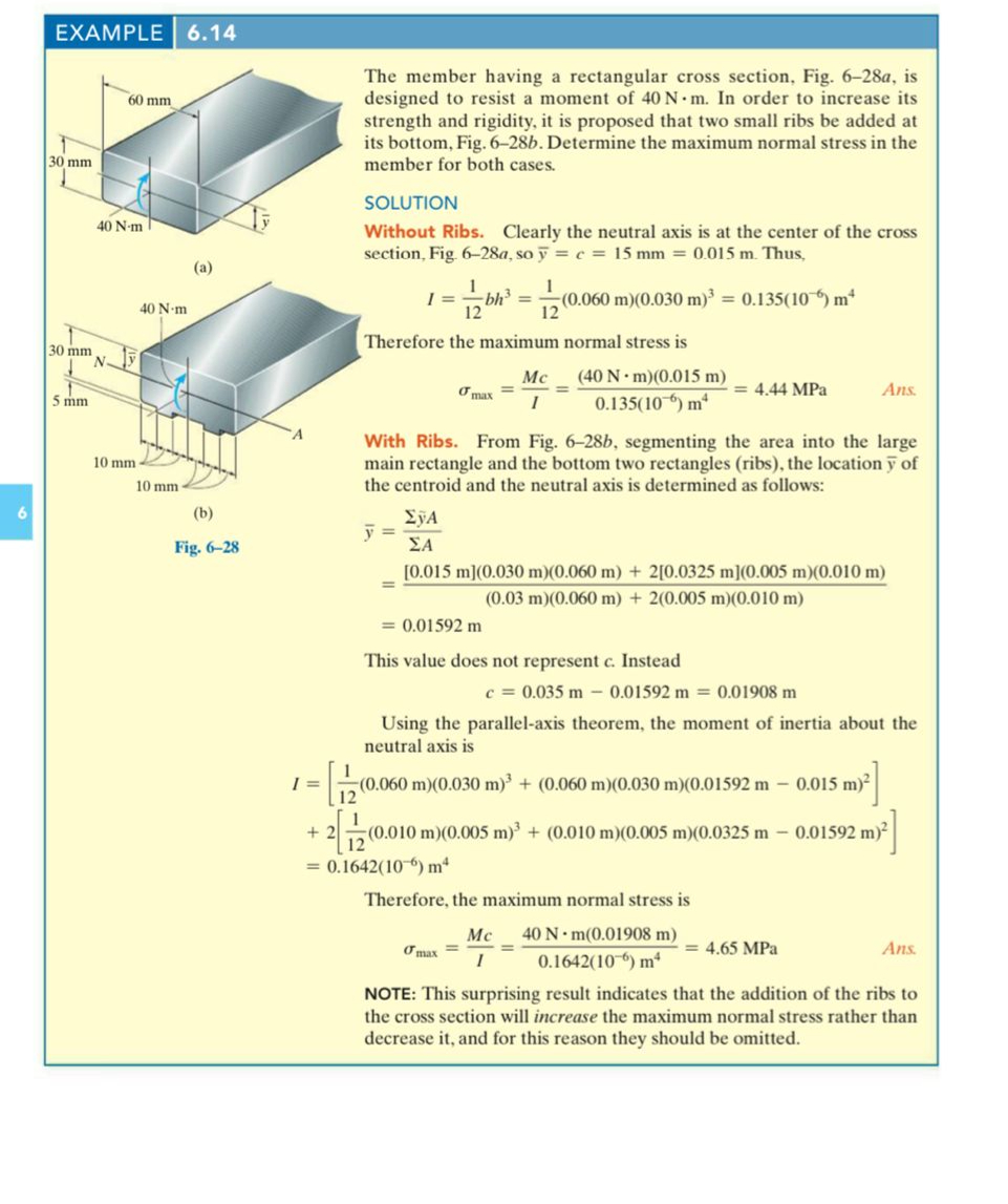
designed to resist a moment of In order to increase its
strength and rigidity, it is proposed that two small ribs be added at
its bottom, Fig. b Determine the maximum normal stress in the
member for both cases.
SOLUTION
Without Ribs. Clearly the neutral axis is at the center of the cross
section, Fig. a so Thus,
Therefore the maximum normal stress is
MPa
With Ribs. From Fig. b segmenting the area into the large
main rectangle and the bottom two rectangles ribs the location of
the centroid and the neutral axis is determined as follows:
This value does not represent Instead
Using the parallelaxis theorem, the moment of inertia about the
neutral axis is
Therefore, the maximum normal stress is
MPa
NOTE: This surprising result indicates that the addition of the ribs to
the cross section will increase the maximum normal stress rather than
decrease it and for this reason they should be omitted.
Step by Step Solution
There are 3 Steps involved in it
1 Expert Approved Answer
Step: 1 Unlock

Question Has Been Solved by an Expert!
Get step-by-step solutions from verified subject matter experts
Step: 2 Unlock
Step: 3 Unlock