

The MIL1 shown in the figure is rotated at a speed of 2700 rpm. Power transmission between
Question:
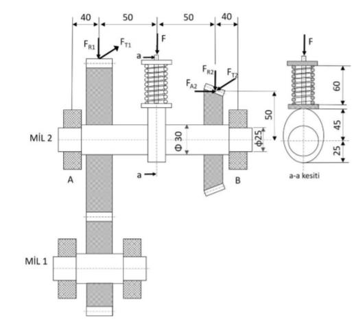
The MIL1 shown in the figure is rotated at a speed of 2700 rpm. Power transmission between MIL1 and MIL2 is provided by spur gear wheels with tooth numbers and modules z1 = 14 and z2 = 42 and m = 6 mm, respectively. While the gears are being manufactured, the middle plane of the set is provided to coincide with the rolling circle of the gears. Apart from the spur gear, there is a cam profile on the shaft 2. The dimensions of this profile are shown in section a-a. F = 200 N force will be applied to another machine element with full compression of the spring while working with the cam profile. In order to provide the necessary working conditions, a spring with a wire diameter of 4 mm, a free length of 90 mm and with both ends paralleled to the arc diameter is used. It is made of a material with a spring shear modulus of elasticity of 79 GPa. The permissible safe fatigue limit in the case of continuous strength of the spring material is given as 410 MPa.
It is known that there are Fa2 = 440N, Fr2 = 380N and Ft2 = 1600N on the bevel gear wheel on the MIL2. There are also Fr1 and Ft1 forces on the spur gear on the MIL2. It is known that there is a relationship Fr1 = Ft1.tg (α0) between these forces. Single row ball bearings are used while bearing the MIL 2. Of these, the bed at the A point has been determined to act as an axially movable (free), and the bed at the B point to act as an axial fixed bearing. According to this;
(a) The diameters of the base of the tooth, the over-tooth rolling circle and the foundation circle of the gear wheels and the distance between the axes.
Calculate
(b) Size the spring and determine the safety factor
(c) For A and B bearings, choose a fixed ball bearing with Lh = 12000 hours.
Expert Answer:


Vector Mechanics for Engineers Statics and Dynamics
ISBN: 978-0073212227
8th Edition
Authors: Ferdinand Beer, E. Russell Johnston, Jr., Elliot Eisenberg, William Clausen, David Mazurek, Phillip Cornwell
