

Question: The op-amp circuit shown below is commonly used as a filter in control systems In the class handout we showed that the output of the
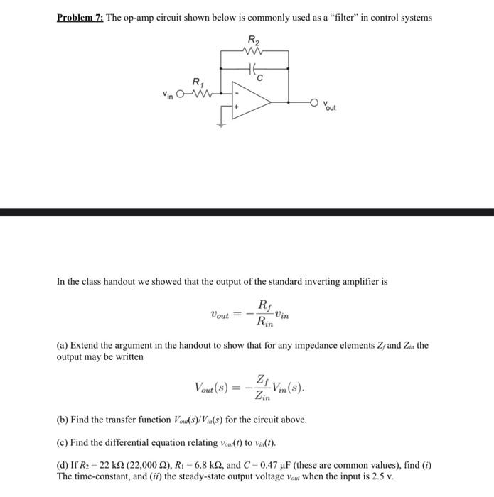
The op-amp circuit shown below is commonly used as a filter in control systems
In the class handout we showed that the output of the standard inverting amplifier is
(a) Extend the argument in the handout to show that for any impedance elements Zf and Zin the output may be written
(b) Find the transfer function Vout(s)/Vin(s) for the circuit above. (c) Find the differential equation relating vout(t) to vin(t).
(d) If R2 = 22 k (22,000 ), R1 = 6.8 k, and C = 0.47 F (these are common values), find (i) The time-constant, and (ii) the steady-state output voltage vout when the input is 2.5 v.
Problem 7: The op-amp circuit shown below is commonly used as a "filter" in control systems In the class handout we showed that the output of the standard inverting amplifier is vout=RinRfvin (a) Extend the argument in the handout to show that for any impedance elements Zf and Zin the output may be written Vout(s)=ZinZfVin(s) (b) Find the transfer function Vour(s)/Vin(s) for the circuit above. (c) Find the differential equation relating vour(t) to vin(t). (d) If R2=22k(22,000),R1=6.8k, and C=0.47F (these are common values), find (i) The time-constant, and (ii) the steady-state output voltage vout when the input is 2.5v
Step by Step Solution
There are 3 Steps involved in it
1 Expert Approved Answer
Step: 1 Unlock

Question Has Been Solved by an Expert!
Get step-by-step solutions from verified subject matter experts
Step: 2 Unlock
Step: 3 Unlock