

Question: The pipe shown in Figure 2 is fixed at end A , which is centered on the origin and can rotate around that point. A
The pipe shown in Figure is fixed at end which is centered on the origin and
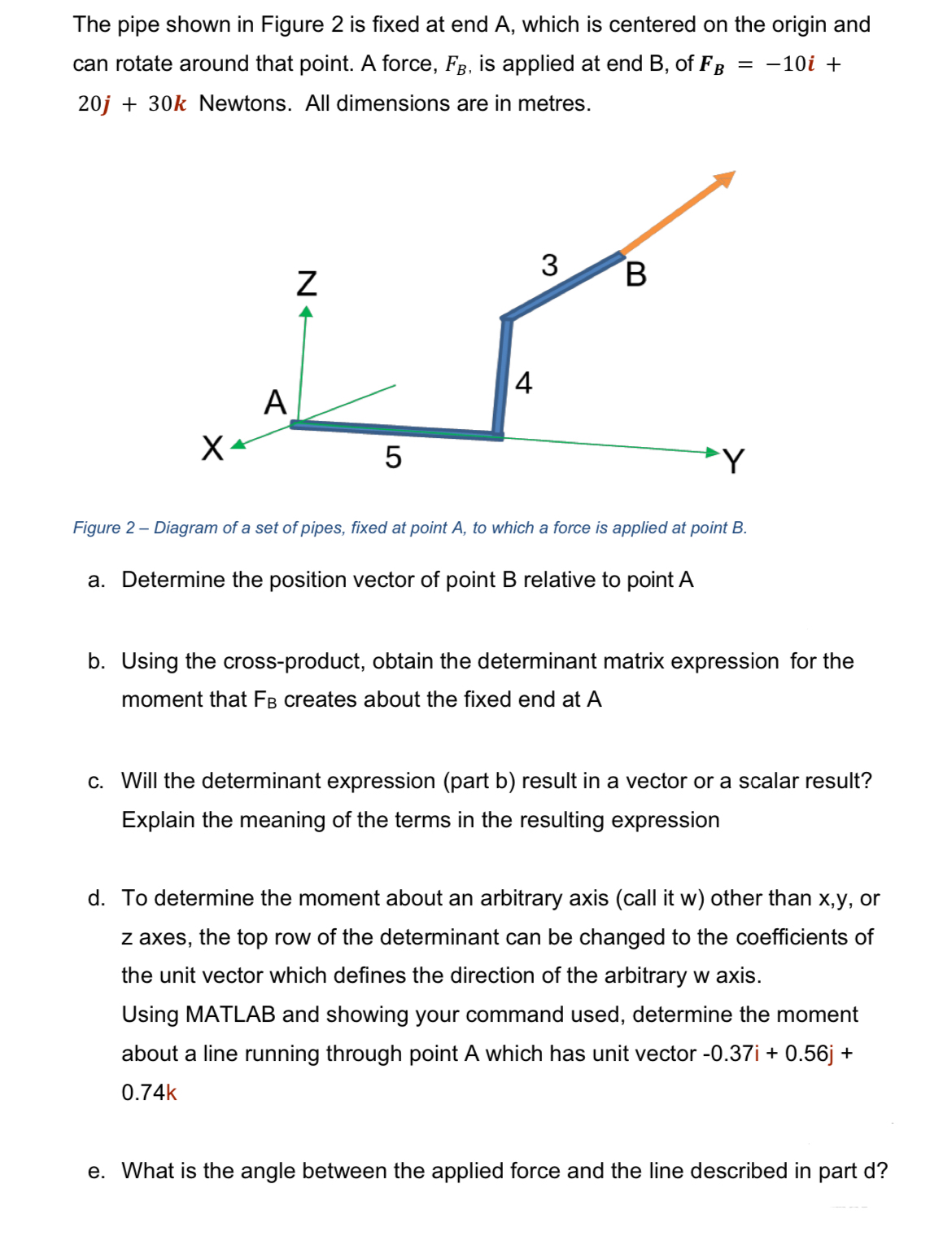
can rotate around that point. A force, is applied at end B of
Newtons. All dimensions are in metres.
Figure Diagram of a set of pipes, fixed at point to which a force is applied at point
a Determine the position vector of point relative to point
b Using the crossproduct, obtain the determinant matrix expression for the
moment that creates about the fixed end at
c Will the determinant expression part b result in a vector or a scalar result?
Explain the meaning of the terms in the resulting expression
d To determine the moment about an arbitrary axis call it other than or
axes, the top row of the determinant can be changed to the coefficients of
the unit vector which defines the direction of the arbitrary w axis.
Using MATLAB and showing your command used, determine the moment
about a line running through point A which has unit vector
k
e What is the angle between the applied force and the line described in part d
Step by Step Solution
There are 3 Steps involved in it
1 Expert Approved Answer
Step: 1 Unlock

Question Has Been Solved by an Expert!
Get step-by-step solutions from verified subject matter experts
Step: 2 Unlock
Step: 3 Unlock