

Question: The primary control objective is to control the polymer product melt viscosity. Two input variables, the reactor temperature and the mole fraction of the chain
The primary control objective is to control the polymer product melt viscosity. Two input variables, the reactor temperature and the mole fraction of the chain transfer agent in the reactor, are available for this purpose. However, because the mole fraction of the chain transfer agent affects the melt viscosity on a much slower time scale compared to the re- actor temperature, reactor temperature is used as the primary control variable when close to steady-state operating conditions. An approximate model for this aspect of the process under such conditions is given by
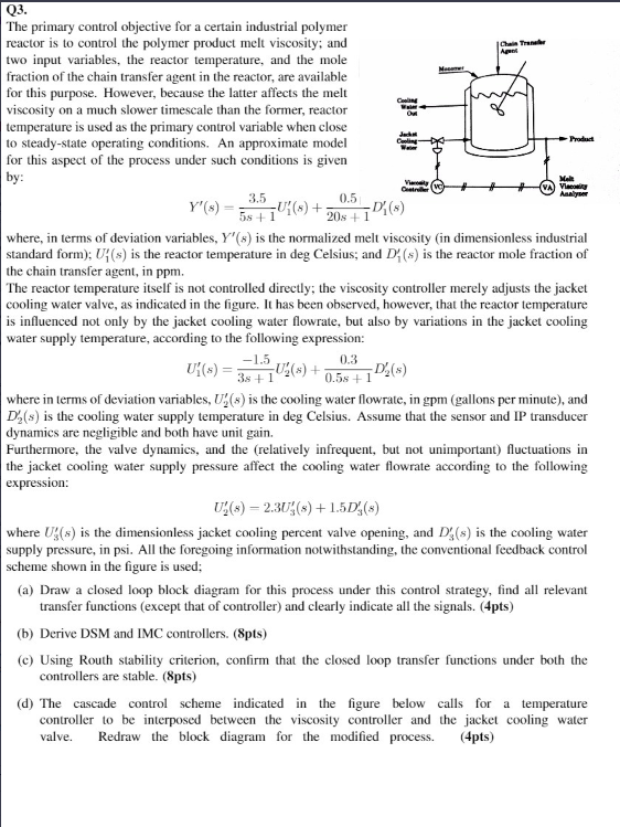
The primary control objective for a certain industrial polymer reactor is to control the polymer product melt viscosity; and two input variables, the reactor temperature, and the mole fraction of the chain transfer agent in the reactor, are available for this purpose. However, because the latter affects the melt viscosity on a much slower timescale than the former, reactor temperature is used as the primary control variable when close to steady-state operating conditions. An approximate model for this aspect of the process under such conditions is given by: Y(s)=5s+13.5U1(s)+20s+10.51(s) where, in terms of deviation variables, Y(s) is the normalized melt viscosity (in dimensionless industrial standard form); U1(s) is the reactor temperature in deg Celsius; and D1(s) is the reactor mole fraction of the chain transfer agent, in ppm. The reactor temperature itself is not controlled directly; the viscosity controller merely adjusts the jacket cooling water valve, as indicated in the figure. It has been observed, however, that the reactor temperature is influenced not only by the jacket cooling water flowrate, but also by variations in the jacket cooling water supply temperature, according to the following expression: U1(s)=3s+11.5U2(s)+0.5s+10.3D2(s) where in terms of deviation variables, U2(s) is the cooling water flowrate, in gpm (gallons per minute), and D2(s) is the cooling water supply temperature in deg Celsius. Assume that the sensor and IP transducer dynamics are negligible and both have unit gain. Furthermore, the valve dynamics, and the (relatively infrequent, but not unimportant) fluctuations in the jacket cooling water supply pressure affect the cooling water flowrate according to the following expression: U2(s)=2.3U3(s)+1.5D3(s) where U3(s) is the dimensionless jacket cooling percent valve opening, and D3(s) is the cooling water supply pressure, in psi. All the foregoing information notwithstanding, the conventional feedback control scheme shown in the figure is used; (a) Draw a closed loop block diagram for this process under this control strategy, find all relevant transfer functions (except that of controller) and clearly indicate all the signals. (4pts) (b) Derive DSM and IMC controllers. (8pts) (c) Using Routh stability criterion, confirm that the closed loop transfer functions under both the controllers are stable. (8pts) (d) The cascade control scheme indicated in the figure below calls for a temperature controller to be interposed between the viscosity controller and the jacket cooling water valve. Redraw the block diagram for the modified process. (4pts) The primary control objective for a certain industrial polymer reactor is to control the polymer product melt viscosity; and two input variables, the reactor temperature, and the mole fraction of the chain transfer agent in the reactor, are available for this purpose. However, because the latter affects the melt viscosity on a much slower timescale than the former, reactor temperature is used as the primary control variable when close to steady-state operating conditions. An approximate model for this aspect of the process under such conditions is given by: Y(s)=5s+13.5U1(s)+20s+10.51(s) where, in terms of deviation variables, Y(s) is the normalized melt viscosity (in dimensionless industrial standard form); U1(s) is the reactor temperature in deg Celsius; and D1(s) is the reactor mole fraction of the chain transfer agent, in ppm. The reactor temperature itself is not controlled directly; the viscosity controller merely adjusts the jacket cooling water valve, as indicated in the figure. It has been observed, however, that the reactor temperature is influenced not only by the jacket cooling water flowrate, but also by variations in the jacket cooling water supply temperature, according to the following expression: U1(s)=3s+11.5U2(s)+0.5s+10.3D2(s) where in terms of deviation variables, U2(s) is the cooling water flowrate, in gpm (gallons per minute), and D2(s) is the cooling water supply temperature in deg Celsius. Assume that the sensor and IP transducer dynamics are negligible and both have unit gain. Furthermore, the valve dynamics, and the (relatively infrequent, but not unimportant) fluctuations in the jacket cooling water supply pressure affect the cooling water flowrate according to the following expression: U2(s)=2.3U3(s)+1.5D3(s) where U3(s) is the dimensionless jacket cooling percent valve opening, and D3(s) is the cooling water supply pressure, in psi. All the foregoing information notwithstanding, the conventional feedback control scheme shown in the figure is used; (a) Draw a closed loop block diagram for this process under this control strategy, find all relevant transfer functions (except that of controller) and clearly indicate all the signals. (4pts) (b) Derive DSM and IMC controllers. (8pts) (c) Using Routh stability criterion, confirm that the closed loop transfer functions under both the controllers are stable. (8pts) (d) The cascade control scheme indicated in the figure below calls for a temperature controller to be interposed between the viscosity controller and the jacket cooling water valve. Redraw the block diagram for the modified process. (4pts)
Step by Step Solution
There are 3 Steps involved in it

Get step-by-step solutions from verified subject matter experts