Question: The proposed system will be used to bake two different types of cookies that will be produced by the confectionary, ideally with no required interaction
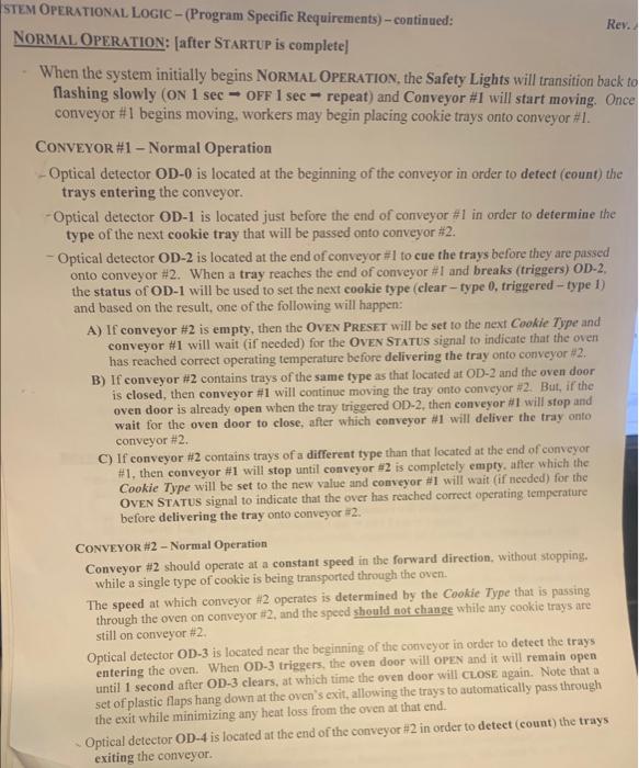
The proposed system will be used to bake two different types of cookies that will be produced by the confectionary, ideally with no required interaction (during normal operation) from the productionline workers once the system is operational. The system consists of two conveyor units, each of which performs an important function with respect to the overall operation of the system (see Figure l): 1) Identification/Cueing of Cookie Trays, and 2) Baking of the Cookies. CONVEYOR \#1 - Identification/Cueing Production line workers, located at the "prep area", place the raw cookic material in special baking trays and then slide the trays onto conveyor #1 to begin the baking process. The trays travel down to the end of conveyor one where they are held in-cue until conveyor $2 is ready to receive them. Additionally, optical detectors located at the end of conveyor #1 are used to detect the type of cookie that is cued for baking. CONVEYOR 42 - Baking Conveyor H2 slowly transports the trays through the long oven that is used to bake the cookies and then pushes the trays onto the "cooldown \& packaging" platform, at which point production line worker will begin to package the cookies. An optical detector, located near the entrance of the oven, is used in conjunction with the detector located at the end of conveyor \#1 to maintain an adequate spacing between the individual baking trays as they are transported through the oven. The rate of travel and the oven. temperature are both based upon the type of cookic being baked, as determined by the optical doteetars lecated at the end of conveyor * 1 . Figure 2 - System Diagram with Optical Detectors snown (rop vnew) CONVEYOR MOTORS \& SUPPLY Both conveyors will be driven by 208V,3,Y-connected, squirrel-eage induction machines: Conveyor 1 needs to be able to operate in both the forward and reverse directions, but only at a single speed, the speed of which is predetermined by the selected motot's gearbox ratio. Since the conveyor only operates at one speed, a confactor-bused supply will be utilized for its motor. Conveyor #2 needs to be able to operate in both the forward and reverse directions and at a variety. of speeds. For this reason, an Allen-Bradley, PowerFlex 40 VFD will be used to supply the drive motor of conveyor $2. 3 - 4530 - Industrial Motor Control Fall 2022 - Programming Assignment (Rev. The oven is an integral part of conveyor \#2. It is used to bake the cookies that have been plac within the specialty baking trays as they travel from the "prep area" to the "packaging".locatic Although the design and detailed operation of the oven is outside the scope of this assignment, th PLC that is controlling the conveyor system must also control the operation of the oven. When it is time for the oven to operate, a +24Voc signal must be sent to the "OVEN ENERGIZE' terminal of the oven's controller in order for the oven's heating elements, circulation fans, and control system to be energized. Once energized, the oven will begin heating to the temperature required by the cookie-type, as defined by a second signal (0VDC Type 0,+24VDC Type 1) that must be sent to the "OVEN PRESET" terminal of the oven's controller. Additionally, the operational status of the oven will be denoted by a signal that the oven will provide at the "OVEN STATUS" terminal of the oven's controller. When either deenergized or energized but not at the correct operating temperature, 0 Voc will be present at the oven's "OVEN STATUS" terminal. But if the oven has reached the correct temperature after being energized, +24V0c will be present at the oven's "OVEN STATUS" terminal. SAFETY DEVICES The system utilizes a set of Safety Lights and a Signal Horn to provide both visual and audible indication of the system's operational state. These devices are directly wired to and thus. energized/controlled by the output module of the PLC. CONTROL PANELS The system contains a two control panels, CP=1 and CP+2. CPH1 is located near the entrance of conveyor "1. This control panel contains two pushbuttons (START and STOP) that are directly connected to the PLC's input module and five indicator lamps that are directly wired to the PLC's output module. CPH2 is located near the exit of conveyor =2. This control panel only contains one pushbutton (REvErSE) that is directly connected to the PLC's input module and five indicator lamps that are directly wired to the PLC's output module. Note that, although both control panels would normally also contain at least one additional pushbutton (EMERGENCY STOP) and additional indicators, the operational logic required for the system to include Emergency Stop and any other functions is outside the scope of this project, and thus the additional buttons and indicators have been omitred from the control panels. OPTICAL DETECTORS The Optical Detectors utilized in this system are beam-type detectors that trigger when an object breaks their light-beam. Each detector contains a NO/NC contact pair that both actuate when the detector is triggered. The detectors' NO contacts will be connected to the PLC's input module such +24VDc will be supplied to the associated input whenever an object breaks a specific detector's beam. OPERATIONAL. LoGiC - (Program Specific Requirements) - continued: RMAL OPERATION: [after STARTUP is complete] When the system initially begins NORMAL OPERATION, the Safety Lights will transition bac flashing slowly (ON 1sec= OFF 1sec= repeat) and Conveyor \#I will start moving. O; conveyor \#1 begins moving, workers may begin placing cookie trays onto conveyor \#1. CONVEYOR \#1 - Normal Operation - Optical detector OD-0 is located at the beginning of the conveyor in order to detect (count) th trays entering the conveyor. - Optical detector OD-1 is located just before the end of conveyor #1 in order to determine the type of the next cookie tray that will be passed onto conveyor #2. - Optical detector OD-2 is located at the end of conveyor \#1 to cue the trays before they are passed onto conveyor \#2. When a tray reaches the end of conveyor \#I and breaks (triggers) OD-2, the status of OD-1 will be used to set the next cookie type (clear-type 0, friggered - type 1) and based on the result, one of the following will happen: A) If conveyor \#2 is empty, then the OvEN PresET will be set to the next Cookie Type and conveyor \#1 will wait (if needed) for the OvEN STATUS signal to indicate that the oven has reached correct operating temperature before delivering the tray onto conveyor 2. B) If conveyor #2 contains trays of the same type as that located at OD-2 and the oven door is closed, then conveyor #1 will continue moving the tray onto conveyor #2. But, if the oven door is already open when the tray triggered OD2, then conveyor #1 will stop and wait for the oven door to close, after which conveyor #1 will deliver the tray onto conveyor #2. C) If conveyor $2 contains trays of a different type than that located at the end of conveyor #1, then conveyor #1 will stop until conveyor $2 is completely empty, after which the Cookie Type will be set to the new value and conveyor \#I will wait (if needed) for the OvEN STATUS signal to indicate that the over has reached correct operating temperature before delivering the tray onto conveyor =2. CONVEYOR \#2 - Normal Operation Conveyor #2 should operate at a constant speed in the forward direction, without stepping. while a single type of cookie is being transported through the oven. The speed at which conveyor \#2 operates is determined by the Cookie Type that is passing through the oven on conveyor \#2, and the speed should not change while any cookie trays are still on conveyor #2. Optical detector OD-3 is located near the beginning of the conveyor in order to detect the trays entering the oven. When OD-3 triggers, the oven door will oPEN and it will remain open until 1 second after OD-3 clears, at which time the oven door will CLosE again. Note that a set of plastic flaps hang down at the oven's exit, allowing the trays to automatically pass through the exit while minimizing any heat loss from the oven at that end. Optical detector OD-4 is located at the end of the conveyor #2 in order to deteet (count) the trays exiting the conveyor. M OPERATIONAL LOGIC - (Program Specific Requirements) - continued: IUTDOWN: [From "Normal Operation"] Pressing and holding the STOP button for (at least) 2 seconds will cause the System Shutdow indicator to illuminate, the Normal Operation indicator to shut off, and the following set of ordered events to occur: a) The Safety Lights will begin flashing faster (ON 1/2secO OF 1/2sec repeat), b) The Safety Horn will sound (ON) for 2 seconds. Once all of the trays on conveyor #1 have been moved onto conveyor #2 (i.c. #1 is empty): c) Conveyor \#1 will stop. d) The Safety Horn will sound (ON) for 1 second. Once all of the remaining trays have been moved off of conveyor #2 (i.e, $2 is empty): e) The over door will opEN, and the oven will de-energize. f) The Safety Horn will sound (ON) for 3 seconds. Once the 3-second Safety Horn finishes sounding, the Safety Lights will transition back to flashing slowly (ON 1 sec - OFF 1 sec - repeat) and will continue flashing for a total of 6 seconds, after which: g) Conveyor \#2 will stop. h) The Safety Horn will sound (ov) for 1 second. i) The Safety Lights will stop flashing (and will remain OFF) and the System Operarional indicator will turn OFF. When steps a-i are complete, the system is considered to be fully de-energized and should be able to either be re-started normally or reverse-started as described below: REVERSE OPERATION: [from a fully de-energized state] If the system is fully de-energized and the Reverse button is pressed and held-in for at least 2 seconds, then the system will go into REvERSE OPRRATION mode as follows: a) The System Operational and System Starting indicators will both tum ox. b) The Safety Light will begin flashing (ov I sec - off 1 sec - repeat). c) The Safety Horn will sound (ox) for 4 seconds, stop (OFF) for 1 second, and then sound again for 1 second. d) Both conveyors will begin moving in the reverse direction. The system will remain operating in the reverse direction until both coavcyors have been empty for 10 seconds, at which time: e) The Safety Horn will sound (ov) for 2 seconds. f) The Safety Light will stop flashing (and it will remain orr) g) The System Operational and System Starting indicators will both tum ofF. When steps a-g are complete, the system is considered to be fully de-energized. Note - while in REvERSE OPERITION, pressing cither the STaRT or Sror button will have no effect. Improper Button Presses Care should be taken to ensure that any improper button presses will not cause improper system operation. 1.e. - the REVERSE button should have no effect unless the system is fully de-energized, and the START button should have no effect while the system is in Norval OpErstoo, SHUTDOWN, or REvERSE. 8=