

Question: The required steps, process, diagrams, and / or unknowns are specified below. The plane rigid frame is carrying loads as shown in Fig. 2 .
The required steps, process, diagrams, andor unknowns are specified below.
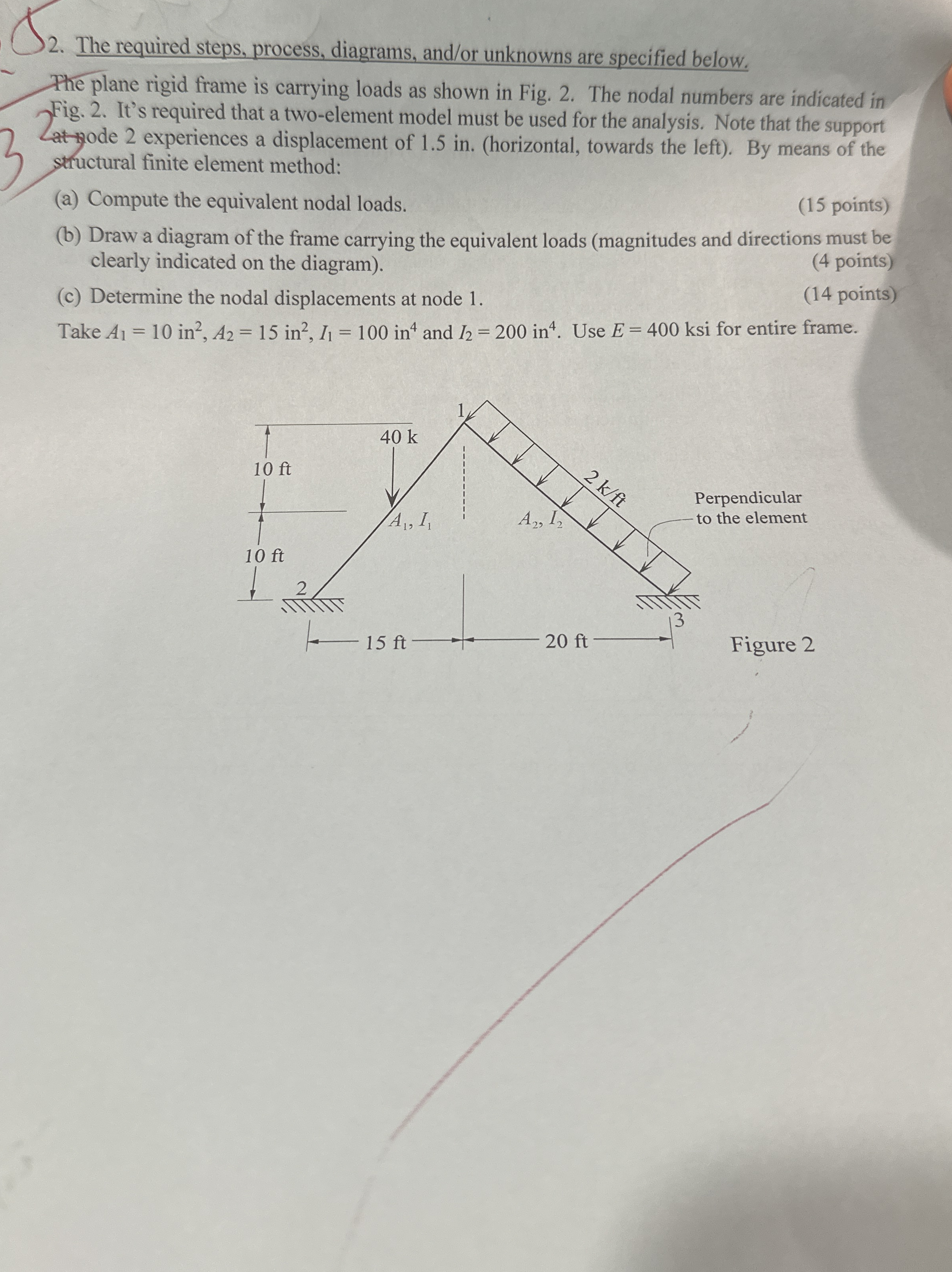
The plane rigid frame is carrying loads as shown in Fig. The nodal numbers are indicated in Fig. It's required that a twoelement model must be used for the analysis. Note that the support Lat wode experiences a displacement of in horizontal towards the left By means of the structural finite element method:
a Compute the equivalent nodal loads.
points
b Draw a diagram of the frame carrying the equivalent loads magnitudes and directions must be clearly indicated on the diagram
points
c Determine the nodal displacements at node
points
Take and Use ksi for entire frame.
Step by Step Solution
There are 3 Steps involved in it
1 Expert Approved Answer
Step: 1 Unlock

Question Has Been Solved by an Expert!
Get step-by-step solutions from verified subject matter experts
Step: 2 Unlock
Step: 3 Unlock