

Question: The required steps, process, diagrams, and / or unknowns are specified below. The plane truss is shown in Fig. 3 . The nodal numbers and
The required steps, process, diagrams, andor unknowns are specified below.
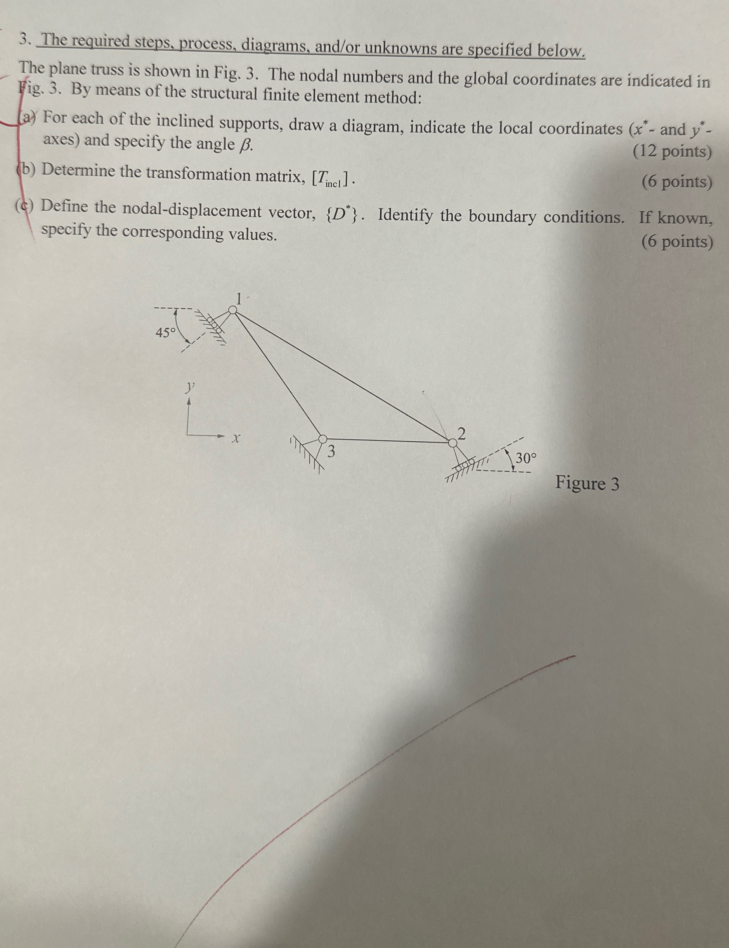
The plane truss is shown in Fig. The nodal numbers and the global coordinates are indicated in Fig. By means of the structural finite element method:
a For each of the inclined supports, draw a diagram, indicate the local coordinates and axes and specify the angle
b Determine the transformation matrix,
points
points
c Define the nodaldisplacement vector, Identify the boundary conditions. If known, specify the corresponding values.
points
Step by Step Solution
There are 3 Steps involved in it
1 Expert Approved Answer
Step: 1 Unlock

Question Has Been Solved by an Expert!
Get step-by-step solutions from verified subject matter experts
Step: 2 Unlock
Step: 3 Unlock