

Question: The shaft shown in the figure below is driven by a gear at the right keyway, drives a fan at the left keyway, and is
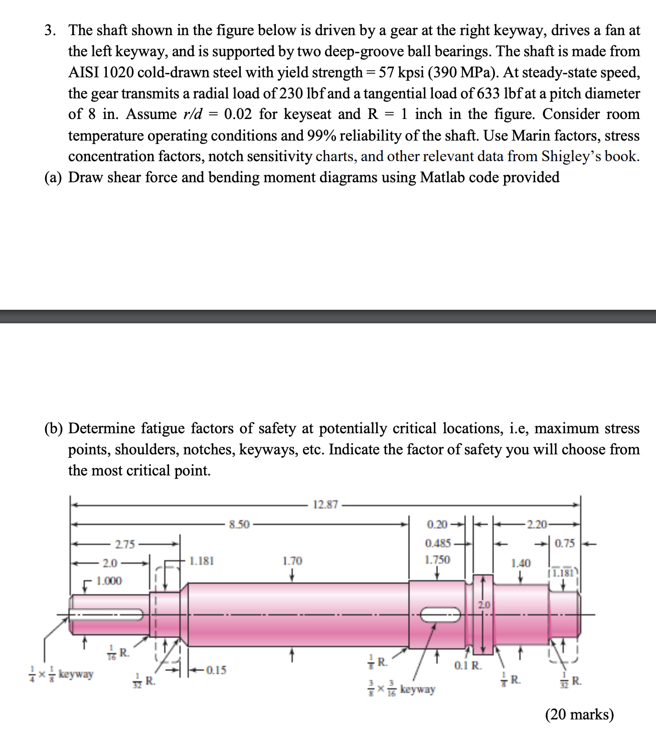
The shaft shown in the figure below is driven by a gear at the right keyway, drives a fan at
the left keyway, and is supported by two deepgroove ball bearings. The shaft is made from
AISI colddrawn steel with yield strength MPa At steadystate speed,
the gear transmits a radial load of lbf and a tangential load of lbf at a pitch diameter
of in Assume for keyseat and inch in the figure. Consider room
temperature operating conditions and reliability of the shaft. Use Marin factors, stress
concentration factors, notch sensitivity charts, and other relevant data from Shigley's book.
a Draw shear force and bending moment diagrams using Matlab code provided
b Determine fatigue factors of safety at potentially critical locations, ie maximum stress
points, shoulders, notches, keyways, etc. Indicate the factor of safety you will choose from
the most critical point.
clc;
clear all;
Fill up X array
x::;
x::;
x::;
x::;
Xx;x;x;x;
Fill up Shear force array
V:lengthx;
V:lengthx;
V:lengthx;
V:lengthx;
VFV;V;V;V;
figure; hold on; grid on;
plotXVF;
textXlengthxVFlengthx;
textXlengthxlengthxVFlengthxlengthx
textXlengthxlengthxlengthxVFlengthxlengthxlengthx;
for k:lengthX
MktrapzX:kVF:k;
end
figure; hold on; grid on;
plotXM;
textXlengthxMlengthx;
textXlengthxlengthxMlengthxlengthx
ValLocmaxM;
XLoc;
Location findX & X;
XLocation
MLocation this is the matlab code
marks
Step by Step Solution
There are 3 Steps involved in it
1 Expert Approved Answer
Step: 1 Unlock

Question Has Been Solved by an Expert!
Get step-by-step solutions from verified subject matter experts
Step: 2 Unlock
Step: 3 Unlock