

Question: The stream data for industrial process are summarized in Table 1. Table 1. Stream data for the process Stream Name Supply Temperature (C) Target Temperature
The stream data for industrial process are summarized in Table 1.
Table 1. Stream data for the process
| Stream Name | Supply Temperature (C) | Target Temperature (C) | Heat Capacity Flowrate (kW K1) |
| 1 | 250 | 120 | 15 |
| 2 | 300 | 150 | 9 |
| 3 | 60 | 320 | 8 |
| 4 | 160 | 300 | 5 |
| 5 | 80 | 160 | 10 |
The existing heat exchanger network for this process is shown in Figure 1. The minimum temperature difference of the network is Tmin=20 K. Produce the Grid Diagram of the existing network. Indicate on the diagram the location of the pinch and the flowing heat capacity and heat requirements for each stream.
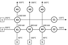
Figure 1. Existing heat exchanger network for the process
C) Determine, from the information in Figure 1, the Grid Diagram in (b) and the values calculated in (a), why the design presented in Figure 1 is sub-optimal and identify the causes. Verify the violations based on the targets calculated.
D) Produce the basic Grid Diagram that is required for the optimal Heat Exchanger Network design (omitting the heat exchangers). Indicate on the diagram the location of the pinch, the flowing heat capacity and the Above- and Below-pinch heat requirements for each stream. Construct CP tables for the Above- and Below-pinch regions
E) Draw a second copy of your grid diagram, then use the provided and derived information to produce a Heat Exchanger Network design for the Above-pinch region. Show all necessary information regarding heat loads, temperatures etc. on the diagram.
F) Draw a third copy of your grid diagram, then use the provided and derived information to produce a Heat Exchanger Network design for the Below-pinch region. Show all necessary information regarding heat loads, temperatures etc. on the diagram.
G) Complete the table below to show the temperatures around each heat exchanger and the heat load from both the Above-pinch and Below-pinch regions, including the required heat loads from hot and cold utility.
| Heat exchanger | Th1 (C) | Th2 (C) | Tc1 (C) | Tc2 (C) | TH/ TC (K) | CPH (kW K1) | CPC (kW K1) | Heat load (kW) |
|
|
|
|
|
|
|
|
|
|
|
|
|
|
|
|
|
|
11100040010000
Step by Step Solution
There are 3 Steps involved in it

Get step-by-step solutions from verified subject matter experts