

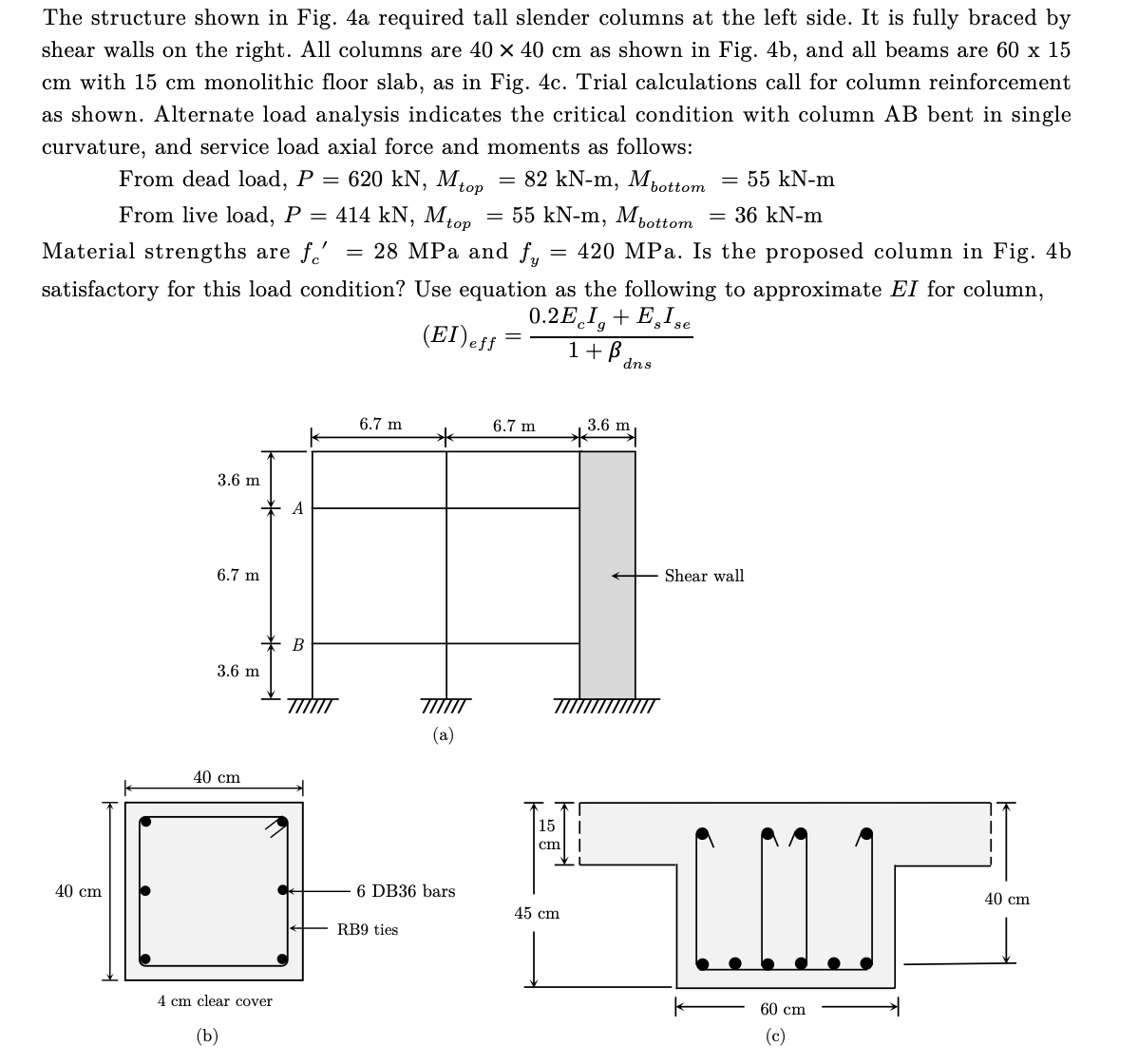
Question: The structure shown in Fig. 4 a required tall slender columns at the left side. It is fully braced by shear walls on the right.
The structure shown in Fig. a required tall slender columns at the left side. It is fully braced by
shear walls on the right. All columns are as shown in Fig. b and all beams are
with monolithic floor slab, as in Fig. c Trial calculations call for column reinforcement
as shown. Alternate load analysis indicates the critical condition with column AB bent in single
curvature, and service load axial force and moments as follows:
From dead load,
From live load,
Material strengths are MPa and MPa. Is the proposed column in Fig. b
satisfactory for this load condition? Use equation as the following to approximate for column,
Step by Step Solution
There are 3 Steps involved in it
1 Expert Approved Answer
Step: 1 Unlock

Question Has Been Solved by an Expert!
Get step-by-step solutions from verified subject matter experts
Step: 2 Unlock
Step: 3 Unlock