

Question: The structure shown in figure 1 a is designed to support ( qquad ) ( mathbf { P }
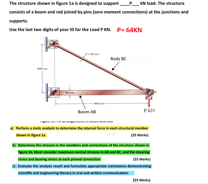
The structure shown in figure a is designed to support qquad mathbfPqquad kN load. The structure consists of a boom and rod joined by pins zero moment connections at the junctions and supports.
Use the last two digits of your ID for the Load P KN PKN
a Perform a static analysis to determine the internal force in each structural member shown in figure a
Marks
b Determine the stresses in the members and connections of the structure shown in
figure b Must consider maximum normal stresses in AB and BC and the shearing stress and bearing stress at each pinned connection
Marks
c Evaluate the analysis result and formulate appropriate conclusions demonstrating scientific and engineering literacy in oral and written communication.
Marks
Step by Step Solution
There are 3 Steps involved in it
1 Expert Approved Answer
Step: 1 Unlock

Question Has Been Solved by an Expert!
Get step-by-step solutions from verified subject matter experts
Step: 2 Unlock
Step: 3 Unlock