

Question: The structure shown in Figure 1 is supported by fixed support at A and roller support at B and D . An internal hinge at
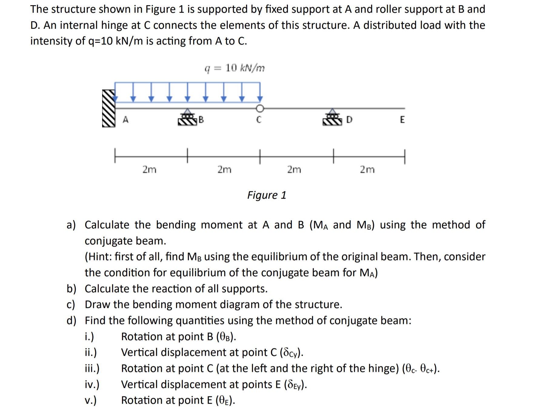
The structure shown in Figure is supported by fixed support at A and roller support at and D An internal hinge at connects the elements of this structure. A distributed load with the intensity of is acting from A to C
a Calculate the bending moment at A and and using the method of conjugate beam.
Hint: first of all, find using the equilibrium of the original beam. Then, consider the condition for equilibrium of the conjugate beam for
b Calculate the reaction of all supports.
c Draw the bending moment diagram of the structure.
d Find the following quantities using the method of conjugate beam:
i Rotation at point
ii Vertical displacement at point
iii. Rotation at point C at the left and the right of the hinge
iv Vertical displacement at points
v Rotation at point
Step by Step Solution
There are 3 Steps involved in it
1 Expert Approved Answer
Step: 1 Unlock

Question Has Been Solved by an Expert!
Get step-by-step solutions from verified subject matter experts
Step: 2 Unlock
Step: 3 Unlock