

Question: The system in Figure 1 is a simple model for a rate gyro, which uses gyroscopic effects to measure yaw rates. The rotor, which spins
The system in Figure is a simple model for a rate gyro, which uses gyroscopic effects to
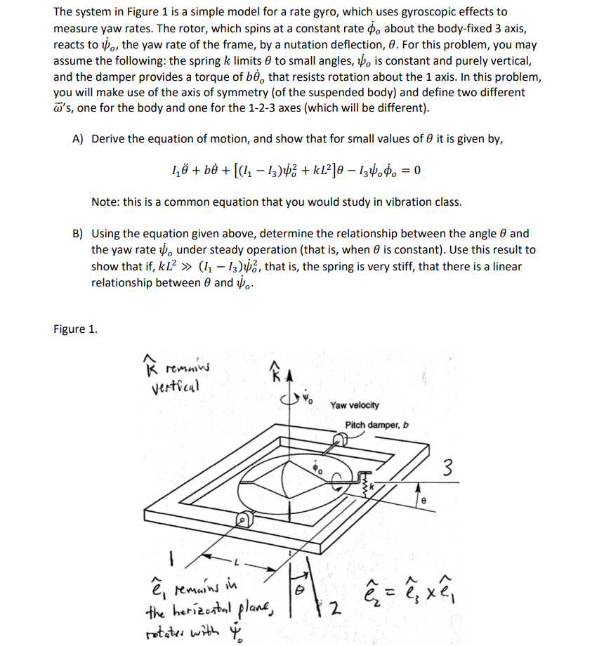
measure yaw rates. The rotor, which spins at a constant rate phi o about the bodyfixed axis,
reacts to psi o the yaw rate of the frame, by a nutation deflection, theta For this problem, you may
assume the following: the spring k limits theta to small angles, psi o is constant and purely vertical,
and the damper provides a torque of btheta o that resists rotation about the axis. In this problem,
you will make use of the axis of symmetry of the suspended body and define two different
vecomega s one for the body and one for the axes which will be different
Atheta it is given by
Itheta btheta IIpsi okLtheta Ipsi ophi o
Note: this is a common equation that you would study in vibration class.
Btheta and
the yaw rate psi otheta is constantkLIIpsi o that is the spring is very stiff, that there is a linear
relationship between theta and psi o
Figure
Step by Step Solution
There are 3 Steps involved in it
1 Expert Approved Answer
Step: 1 Unlock

Question Has Been Solved by an Expert!
Get step-by-step solutions from verified subject matter experts
Step: 2 Unlock
Step: 3 Unlock