

Question: - - - - - - The system shown in Figure 2 . 4 8 is to be arranged by varying h such that water
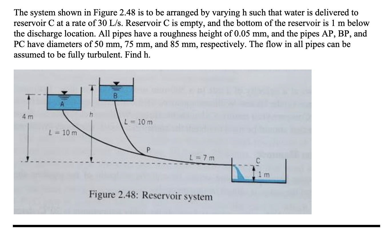
The system shown in Figure is to be arranged by varying such that water is delivered to reservoir at a rate of Reservoir is empty, and the bottom of the reservoir is below the discharge location. All pipes have a roughness height of and the pipes AP BP and have diameters of and respectively. The flow in all pipes can be assumed to be fully turbulent. Find h
Step by Step Solution
There are 3 Steps involved in it
1 Expert Approved Answer
Step: 1 Unlock

Question Has Been Solved by an Expert!
Get step-by-step solutions from verified subject matter experts
Step: 2 Unlock
Step: 3 Unlock