

Question: The table gives dimensions for two different four bar linkages. Link numbering is defined as follows: Link 1 - Ground link Link 2 - Input
The table gives dimensions for two different four bar linkages. Link numbering is defined as follows:
Link Ground link
Link Input link
Link Coupler link
Link Output link
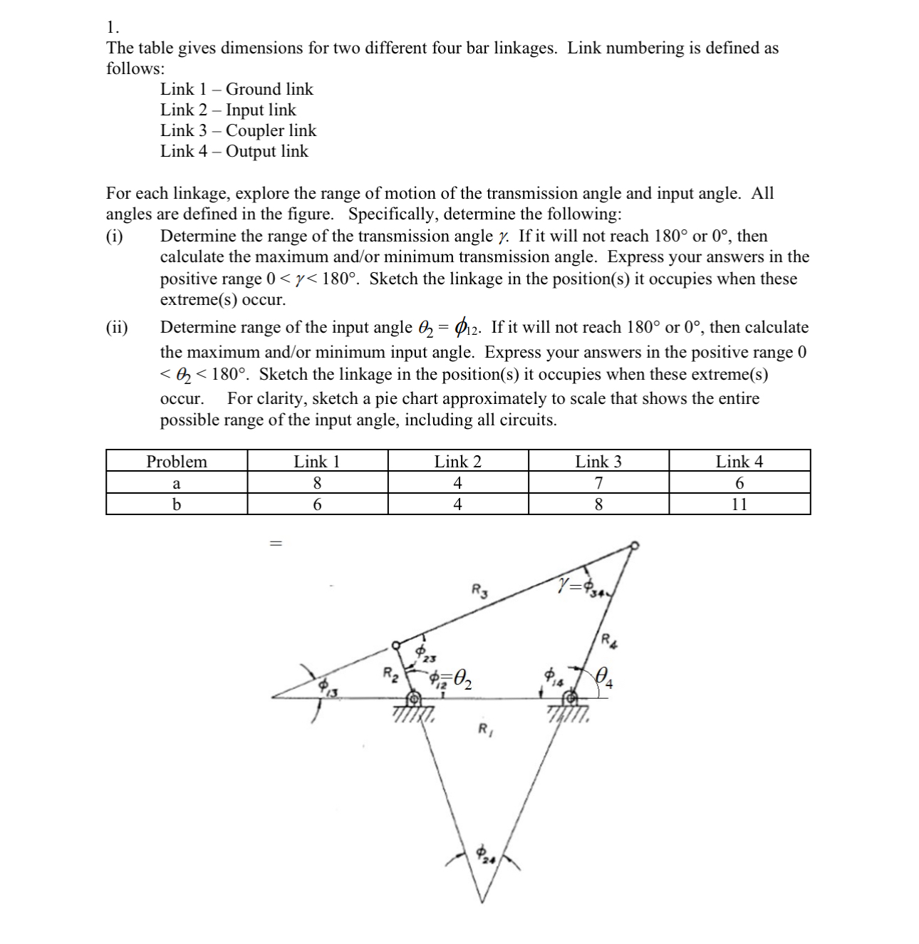
For each linkage, explore the range of motion of the transmission angle and input angle. All angles are defined in the figure. Specifically, determine the following:
i Determine the range of the transmission angle If it will not reach or then calculate the maximum andor minimum transmission angle. Express your answers in the positive range Sketch the linkage in the positions it occupies when these extremes occur.
ii Determine range of the input angle If it will not reach or then calculate the maximum andor minimum input angle. Express your answers in the positive range Sketch the linkage in the positions it occupies when these extremes occur. For clarity, sketch a pie chart approximately to scale that shows the entire possible range of the input angle, including all circuits.
tableProblemLink Link Link Link ab
Step by Step Solution
There are 3 Steps involved in it
1 Expert Approved Answer
Step: 1 Unlock

Question Has Been Solved by an Expert!
Get step-by-step solutions from verified subject matter experts
Step: 2 Unlock
Step: 3 Unlock