

Question: This code is for Arduino. Original code: // Pin assignments // EN (PWM) pins must be one of 3, 5, 6, 9, 10, and 11
This code is for Arduino.
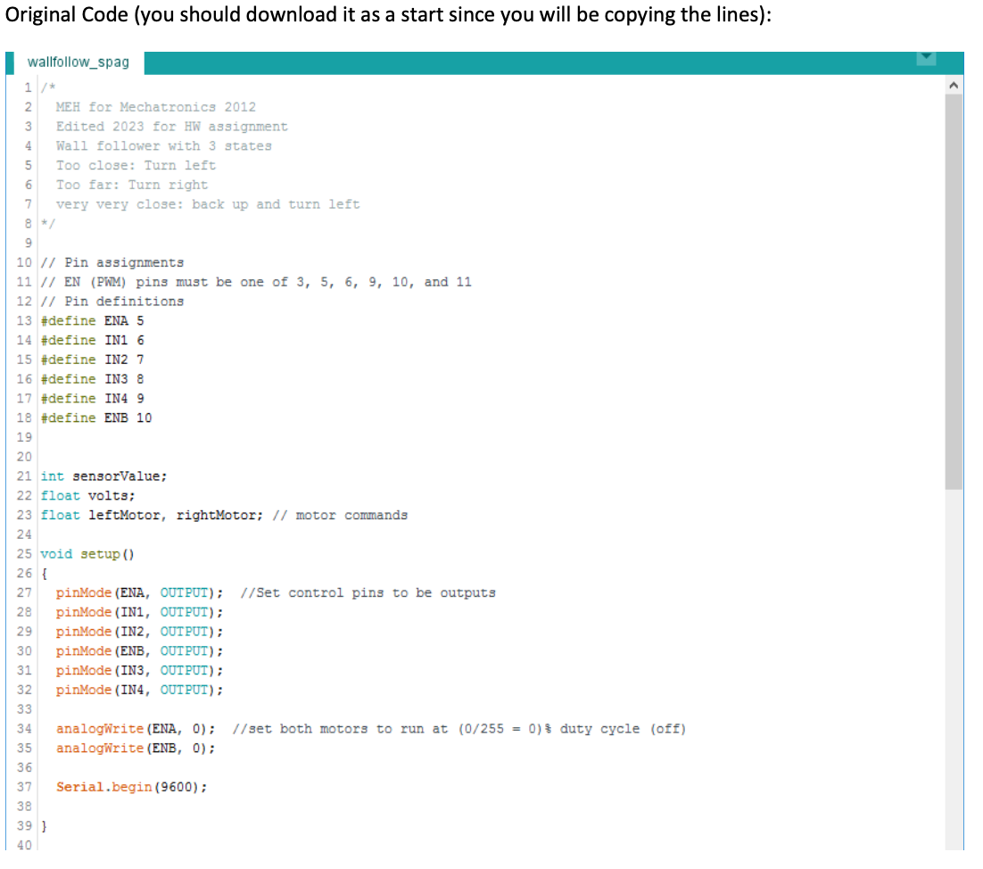
Original code:
// Pin assignments
// EN (PWM) pins must be one of 3, 5, 6, 9, 10, and 11
// Pin definitions
#define ENA 5
#define IN1 6
#define IN2 7
#define IN3 8
#define IN4 9
#define ENB 10
int sensorValue;
float volts;
float leftMotor, rightMotor; // motor commands
void setup()
{
pinMode(ENA, OUTPUT); //Set control pins to be outputs
pinMode(IN1, OUTPUT);
pinMode(IN2, OUTPUT);
pinMode(ENB, OUTPUT);
pinMode(IN3, OUTPUT);
pinMode(IN4, OUTPUT);
analogWrite(ENA, 0); //set both motors to run at (0/255 = 0)% duty cycle (off)
analogWrite(ENB, 0);
Serial.begin(9600);
}
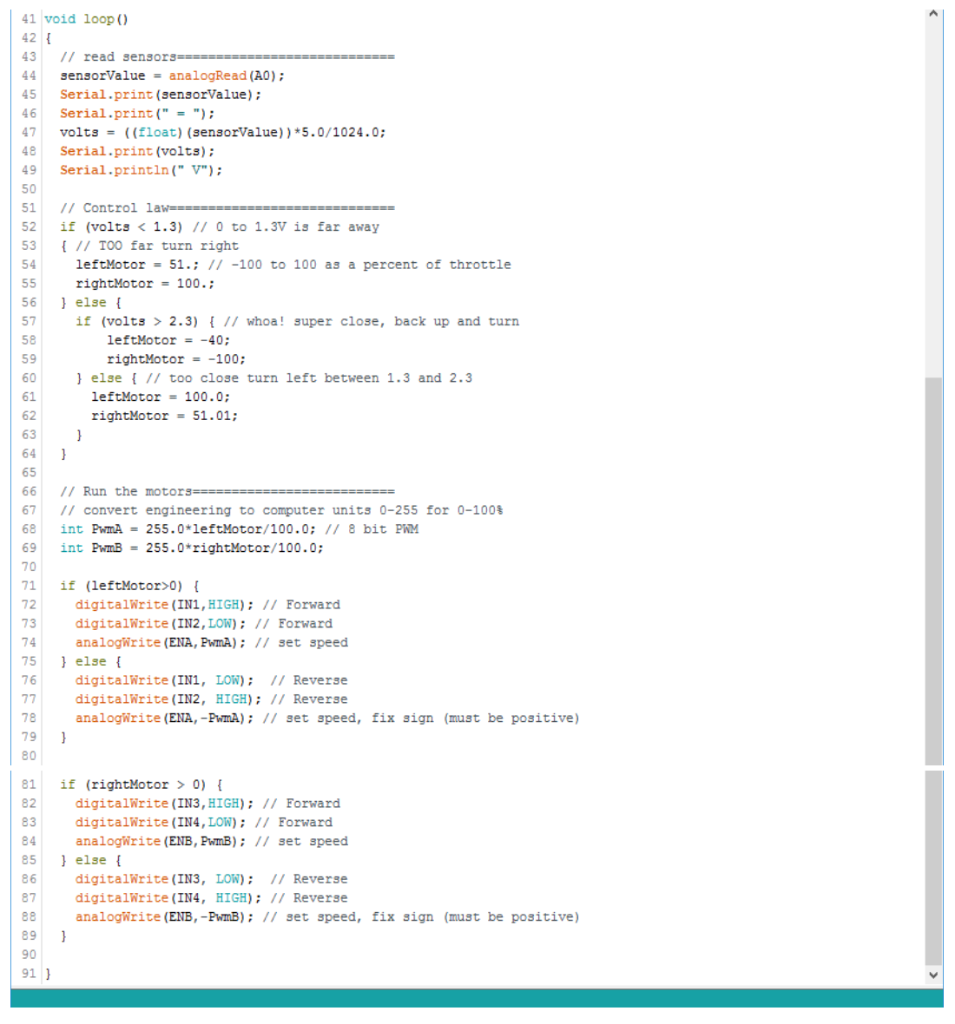
void loop()
{
// read sensors============================
sensorValue = analogRead(A0);
Serial.print(sensorValue);
Serial.print(" = ");
volts = ((float)(sensorValue))*5.0/1024.0;
Serial.print(volts);
Serial.println(" V");
// Control law=============================
if (volts
{ // TOO far turn right
leftMotor = 51.; // -100 to 100 as a percent of throttle
rightMotor = 100.;
} else {
if (volts > 2.3) { // whoa! super close, back up and turn
leftMotor = -40;
rightMotor = -100;
} else { // too close turn left between 1.3 and 2.3
leftMotor = 100.0;
rightMotor = 51.01;
}
}
// Run the motors==========================
// convert engineering to computer units 0-255 for 0-100%
int PwmA = 255.0*leftMotor/100.0; // 8 bit PWM
int PwmB = 255.0*rightMotor/100.0;
if (leftMotor>0) {
digitalWrite(IN1,HIGH); // Forward
digitalWrite(IN2,LOW); // Forward
analogWrite(ENA,PwmA); // set speed
} else {
digitalWrite(IN1, LOW); // Reverse
digitalWrite(IN2, HIGH); // Reverse
analogWrite(ENA,-PwmA); // set speed, fix sign (must be positive)
}
if (rightMotor > 0) {
digitalWrite(IN3,HIGH); // Forward
digitalWrite(IN4,LOW); // Forward
analogWrite(ENB,PwmB); // set speed
} else {
digitalWrite(IN3, LOW); // Reverse
digitalWrite(IN4, HIGH); // Reverse
analogWrite(ENB,-PwmB); // set speed, fix sign (must be positive)
}
}
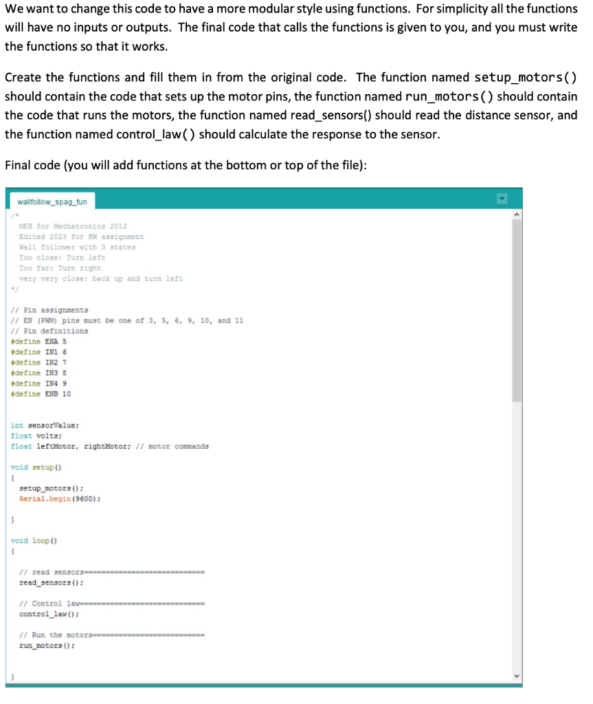
We want to change this code to have a more modular style using functions. For simplicity all the functions will have no inputs or outputs. The final code that calls the functions is given to you, and you must write the functions so that it works. Create the functions and fill them in from the original code. The function named setup_motors() should contain the code that sets up the motor pins, the function named run_motors() should contain the code that runs the motors, the function named read_sensors() should read the distance sensor, and the function named control_law( ) should calculate the response to the sensor. Final code (you will add functions at the bottom or top of the file): wallfollow_spag_fun MEH for Mechacronics 2012 Edited 2023 for HW assignment Wall follower with 3 atates Too close: Turn left Too far: Turn right very very close: back up and turn left 1/ Pin assignments 1/ EN (PhM) ping mugt be one of 3,5,6,9,10, and 11 /1 Pin definitiona 4define ENA 5 \#define IN1 6 Adetine IN2 7 \#detine IN3 8 tdefine INA 9 tdetine ENB 10 int gensorValue; float volts; float leftMotor, rightMotor; // motor cormands void setup() 1 setup_motorg () : Serial. begin (9600); ) void loop() 1 read_sengorg () : control_law(); 1/ Run the motorammennmmennmmmenmmenne run_motora () : Original Code (you should download it as a start since you will be copying the lines): wallfollow_spag
Step by Step Solution
There are 3 Steps involved in it

Get step-by-step solutions from verified subject matter experts