

Question: This is a design problem, there are many acceptable designs. Derive the axial shaft layout from figure 7-12. Design for stress & Choose three critical
This is a design problem, there are many acceptable designs.
Derive the axial shaft layout from figure 7-12.
Design for stress & Choose three critical locations (e.g shoulders, keyways, and grooves etc, depending on the shaft layout one designs). Design shaft diameter and verify the factor of safety for fatigue and yielding for each critical location.
Do force analysis to figure out the supporting forces at the bearings, and the shear force and bending moment diagrams.
Check and adjust for deflection.
Draw resulting shaft design in CAD.
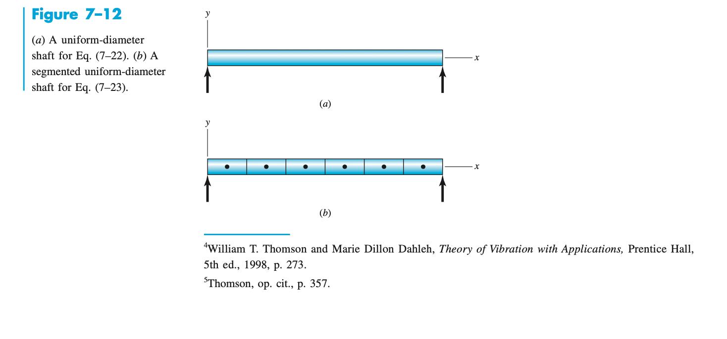
Figure 7-12 (a) A uniform-diameter shaft for Eq. (7-22). (b) A segmented uniform-diameter shaft for Eq. (7-23). y y (a) (b) X X William T. Thomson and Marie Dillon Dahleh, Theory of Vibration with Applications, Prentice Hall, 5th ed., 1998, p. 273. 5Thomson, op. cit., p. 357.
Step by Step Solution
There are 3 Steps involved in it
It appears youve uploaded an image file To proceed with your request I will first ... View full answer

Get step-by-step solutions from verified subject matter experts