

Question: This is a LabVIEW question. Please use LabVIEW to solve it and upload the screenshot of the Labview instead of the handwriting . Problem set
This is a LabVIEW question. Please use LabVIEW to solve it and upload the screenshot of the Labview instead of the handwriting
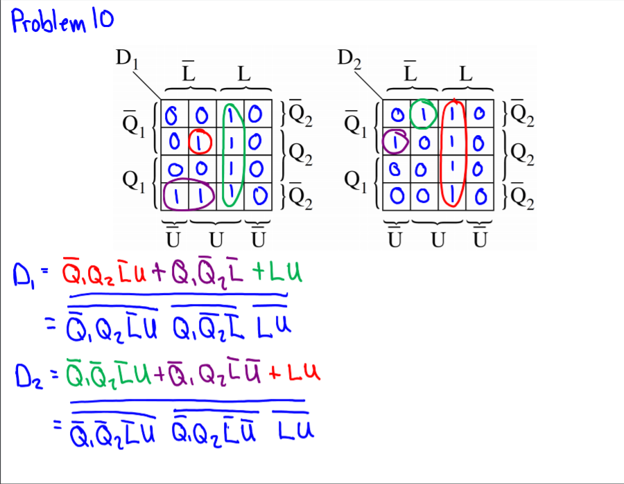
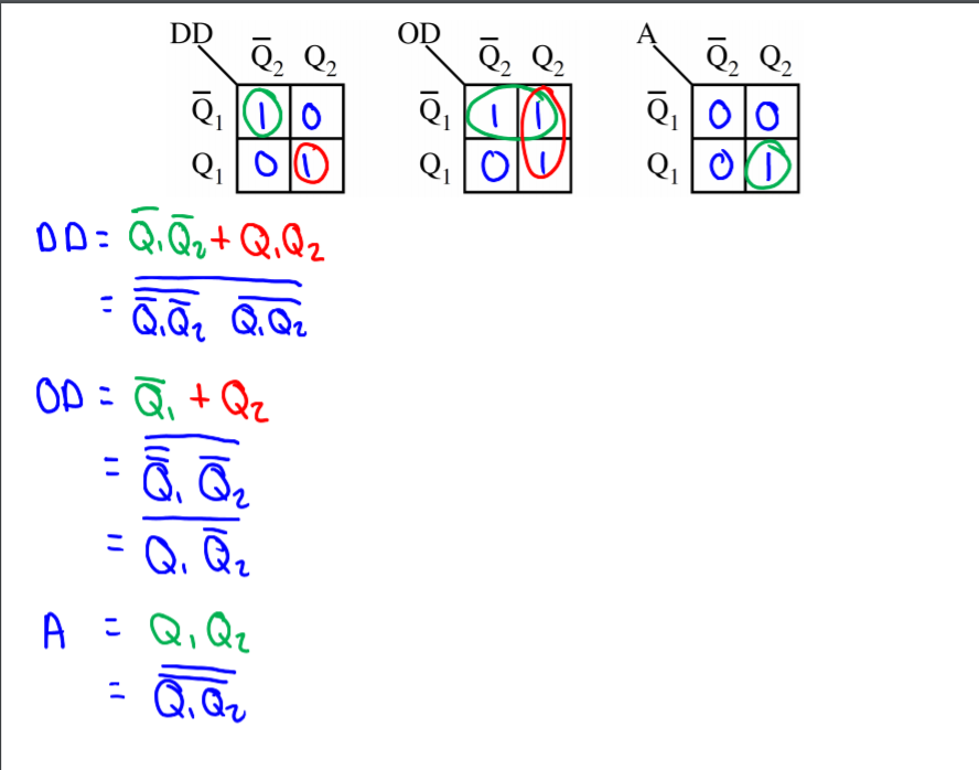
 .Problem set 4, problem 10 solution:
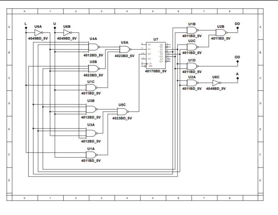
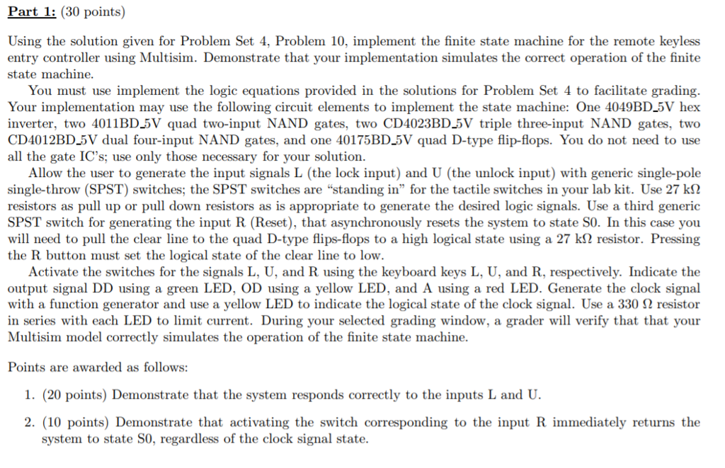
Part 1: (30 points) Using the solution given for Problem Set 4. Problem 10, implement the finite state machine for the remote keyless entry controller using Multisim. Demonstrate that your implementation simulates the correct operation of the finite state machine. You must use implement the logic equations provided in the solutions for Problem Set 4 to facilitate grading. Your implementation may use the following circuit elements to implement the state machine: One 4049BD_5V hex inverter, two 4011BD_5V quad two-input NAND gates, two CD4023BD_5V triple three-input NAND gates, two CD4012BD_5V dual four-input NAND gates, and one 40175BD_5V quad D-type flip-flops. You do not need to use all the gate IC's; use only those necessary for your solution Allow the user to generate the input signals L (the lock input) and U (the unlock input) with generic single-pole single-throw (SPST) switches, the SPST switches arestanding in" for the tactile switches in your lab kit. Use 27 k resistors as pull up or pull down resistors as is appropriate to generate the desired logic signals. Use a third generic SPST switch for generating the input R (Reset), that asynchronously resets the system to state S0. In this case you will need to pull the clear line to the quad D-type flip-flops to a high logical state using a 27 k resistor. Pressing the R button must set the logical state of the clear line to low. Activate the switches for the signals L, U, and R using the keyboard keys L, U, and R, respectively. Indicate the output signal DD using a green LED, OD using a yellow LED, and A using a red LED. Generate the clock signal with a function generator and use a yellow LED to indicate the logical state of the clock signal. Use a 330 resistor in series with each LED to limit current. During your selected grading window, a grader will verify that that your Multisim model correctly simulates the operation of the finite state machine. Points are awarded as follows: 1. (20 points) Demonstrate that the system responds correctly to the inputs L and U. 2. (10 points) Demonstrate that activating the switch corresponding to the input R immediately returns the system to state S0, regardless of the clock signal state Part 1: (30 points) Using the solution given for Problem Set 4. Problem 10, implement the finite state machine for the remote keyless entry controller using Multisim. Demonstrate that your implementation simulates the correct operation of the finite state machine. You must use implement the logic equations provided in the solutions for Problem Set 4 to facilitate grading. Your implementation may use the following circuit elements to implement the state machine: One 4049BD_5V hex inverter, two 4011BD_5V quad two-input NAND gates, two CD4023BD_5V triple three-input NAND gates, two CD4012BD_5V dual four-input NAND gates, and one 40175BD_5V quad D-type flip-flops. You do not need to use all the gate IC's; use only those necessary for your solution Allow the user to generate the input signals L (the lock input) and U (the unlock input) with generic single-pole single-throw (SPST) switches, the SPST switches arestanding in" for the tactile switches in your lab kit. Use 27 k resistors as pull up or pull down resistors as is appropriate to generate the desired logic signals. Use a third generic SPST switch for generating the input R (Reset), that asynchronously resets the system to state S0. In this case you will need to pull the clear line to the quad D-type flip-flops to a high logical state using a 27 k resistor. Pressing the R button must set the logical state of the clear line to low. Activate the switches for the signals L, U, and R using the keyboard keys L, U, and R, respectively. Indicate the output signal DD using a green LED, OD using a yellow LED, and A using a red LED. Generate the clock signal with a function generator and use a yellow LED to indicate the logical state of the clock signal. Use a 330 resistor in series with each LED to limit current. During your selected grading window, a grader will verify that that your Multisim model correctly simulates the operation of the finite state machine. Points are awarded as follows: 1. (20 points) Demonstrate that the system responds correctly to the inputs L and U. 2. (10 points) Demonstrate that activating the switch corresponding to the input R immediately returns the system to state S0, regardless of the clock signal state
Step by Step Solution
There are 3 Steps involved in it

Get step-by-step solutions from verified subject matter experts