

Question: This is a MATLAB Question I am stuck on. Can someone please write the full code (and explaination) for this in MATLAB? Thanks a lot
This is a MATLAB Question I am stuck on.
Can someone please write the full code (and explaination) for this in MATLAB?
Thanks a lot
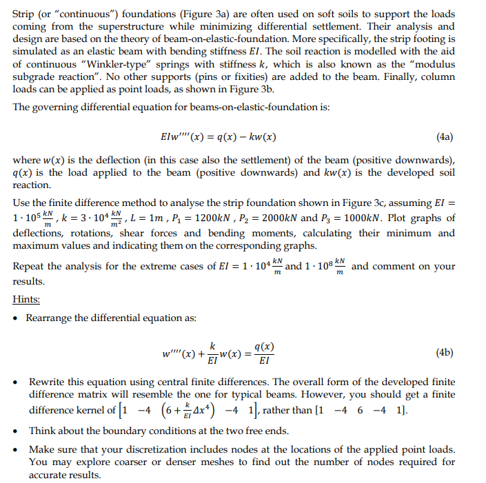
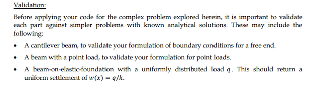
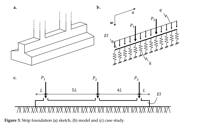
Strip (or continuous) foundations (Figure 3a) are often used on soft soils to support the loads coming from the superstructure while minimizing differential settlement. Their analysis and design are based on the theory of beam-on-elastic-foundation. More specifically, the strip footing is simulated as an elastic beam with bending stiffness El. The soil reaction is modelled with the aid of continuous "Winkler-type springs with stiffness k, which is also known as the modulus subgrade reaction". No other supports (pins or fixities) are added to the beam. Finally, column loads can be applied as point loads, as shown in Figure 3b. The governing differential equation for beams-on-elastic-foundation is: Elw''(x) = 9(x) kw(x) (4a) where w(x) is the deflection (in this case also the settlement) of the beam (positive downwards), 9(x) is the load applied to the beam (positive downwards) and kw(x) is the developed soil reaction. Use the finite difference method to analyse the strip foundation shown in Figure 3c, assuming El 1.105 kW, k = 3. 104 ., L = 1m , Pa = 1200kN , P2 = 2000kN and Pa = 1000kN. Plot graphs of deflections, rotations, shear forces and bending moments, calculating their minimum and maximum values and indicating them on the corresponding graphs. Repeat the analysis for the extreme cases of El = 1.104 kN and 1 108 kN and comment on your results. Hints: Rearrange the differential equation as: m m w"''(x) + q w(x) = 9(x) EI (4b) Rewrite this equation using central finite differences. The overall form of the developed finite difference matrix will resemble the one for typical beams. However, you should get a finite difference kernel of [1 -4 (6+4x) -4 1), rather than [1 -4 6 -4 1). Think about the boundary conditions at the two free ends. Make sure that your discretization includes nodes at the locations of the applied point loads. You may explore coarser or denser meshes to find out the number of nodes required for accurate results. Validation: Before applying your code for the complex problem explored herein, it is important to validate each part against simpler problems with known analytical solutions. These may include the following: A cantilever beam, to validate your formulation of boundary conditions for a free end. A beam with a point load, to validate your formulation for point loads. A beam-on-elastic-foundation with a uniformly distributed load q. This should return a uniform settlement of w(x) = q/k. b. EI W w w W w W w P2 P 5L 4L L XX XX XXX Figure 3. Strip foundation (a) sketch, (b) model and (c) case study. Strip (or continuous) foundations (Figure 3a) are often used on soft soils to support the loads coming from the superstructure while minimizing differential settlement. Their analysis and design are based on the theory of beam-on-elastic-foundation. More specifically, the strip footing is simulated as an elastic beam with bending stiffness El. The soil reaction is modelled with the aid of continuous "Winkler-type springs with stiffness k, which is also known as the modulus subgrade reaction". No other supports (pins or fixities) are added to the beam. Finally, column loads can be applied as point loads, as shown in Figure 3b. The governing differential equation for beams-on-elastic-foundation is: Elw''(x) = 9(x) kw(x) (4a) where w(x) is the deflection (in this case also the settlement) of the beam (positive downwards), 9(x) is the load applied to the beam (positive downwards) and kw(x) is the developed soil reaction. Use the finite difference method to analyse the strip foundation shown in Figure 3c, assuming El 1.105 kW, k = 3. 104 ., L = 1m , Pa = 1200kN , P2 = 2000kN and Pa = 1000kN. Plot graphs of deflections, rotations, shear forces and bending moments, calculating their minimum and maximum values and indicating them on the corresponding graphs. Repeat the analysis for the extreme cases of El = 1.104 kN and 1 108 kN and comment on your results. Hints: Rearrange the differential equation as: m m w"''(x) + q w(x) = 9(x) EI (4b) Rewrite this equation using central finite differences. The overall form of the developed finite difference matrix will resemble the one for typical beams. However, you should get a finite difference kernel of [1 -4 (6+4x) -4 1), rather than [1 -4 6 -4 1). Think about the boundary conditions at the two free ends. Make sure that your discretization includes nodes at the locations of the applied point loads. You may explore coarser or denser meshes to find out the number of nodes required for accurate results. Validation: Before applying your code for the complex problem explored herein, it is important to validate each part against simpler problems with known analytical solutions. These may include the following: A cantilever beam, to validate your formulation of boundary conditions for a free end. A beam with a point load, to validate your formulation for point loads. A beam-on-elastic-foundation with a uniformly distributed load q. This should return a uniform settlement of w(x) = q/k. b. EI W w w W w W w P2 P 5L 4L L XX XX XXX Figure 3. Strip foundation (a) sketch, (b) model and (c) case study
Step by Step Solution
There are 3 Steps involved in it

Get step-by-step solutions from verified subject matter experts