

Question: this is a microcontroller PIC16F877A assembly code While the code below was running an input signal was applied from RBO pin (PORTB,0). Sketch GIE and
this is a microcontroller PIC16F877A assembly code 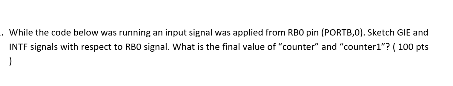
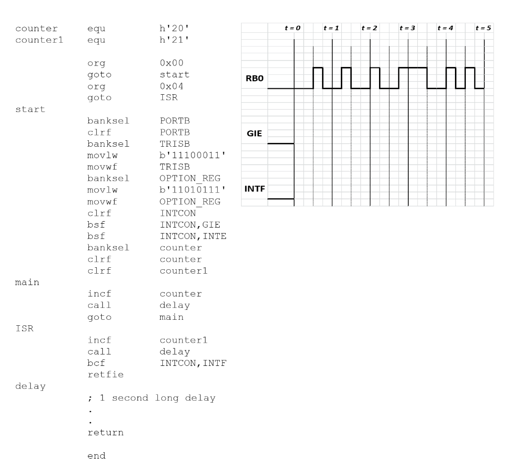
While the code below was running an input signal was applied from RBO pin (PORTB,0). Sketch GIE and INTF signals with respect to RBO signal. What is the final value of counter and counter1? ( 100 pts ) t=0 t=1 t = 2 t = 3 t=4 counter counterl = 4 t = 5 equ equ h'20' h'21' org goto org goto Ox00 start Ox04 ISR hurch RBO start GIE INTE banksel clrf banksel movlw movwf banksel movlw movwf clrf bsf bsf banksel clrf clrf PORTB PORTB TRISB b'11100011' TRISB OPTION REG b'11010111' OPTION REG INTCON INTCON, GIE INTCON, INTE counter counter counterl main incf call goto counter delay main ISR incf call bcf retfie counterl delay INTCON, INTF delay ; 1 second long delay return end While the code below was running an input signal was applied from RBO pin (PORTB,0). Sketch GIE and INTF signals with respect to RBO signal. What is the final value of counter and counter1? ( 100 pts ) t=0 t=1 t = 2 t = 3 t=4 counter counterl = 4 t = 5 equ equ h'20' h'21' org goto org goto Ox00 start Ox04 ISR hurch RBO start GIE INTE banksel clrf banksel movlw movwf banksel movlw movwf clrf bsf bsf banksel clrf clrf PORTB PORTB TRISB b'11100011' TRISB OPTION REG b'11010111' OPTION REG INTCON INTCON, GIE INTCON, INTE counter counter counterl main incf call goto counter delay main ISR incf call bcf retfie counterl delay INTCON, INTF delay ; 1 second long delay return end
Step by Step Solution
There are 3 Steps involved in it

Get step-by-step solutions from verified subject matter experts