

Question: This is python based that is applied to Arduino. ( Seed Studio Grove Starter Kit for Arduino). For input sensors, pls use button(digital) and light
This is python based that is applied to Arduino. ( Seed Studio Grove Starter Kit for Arduino). For input sensors, pls use button(digital) and light sensor(analog) and for output, LED light and LCD screen.
Last 2 pics is the Lab Logbook Template.
I know this may seem like a lot but I would appreciate any help offered. Ty in advance.
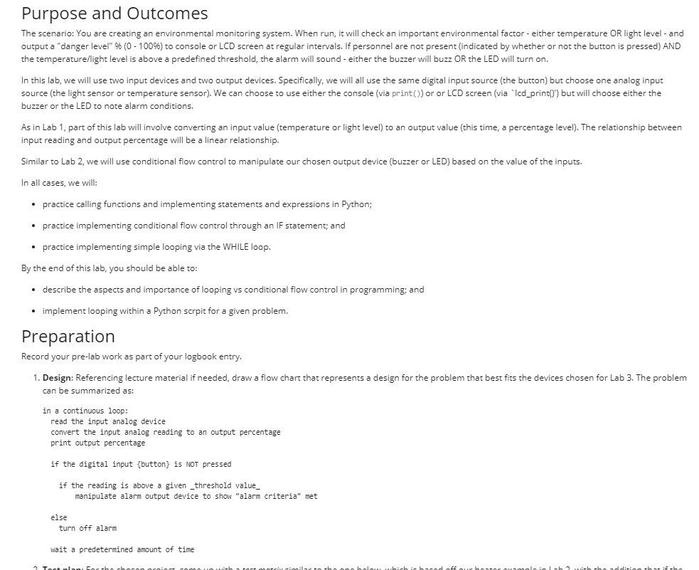
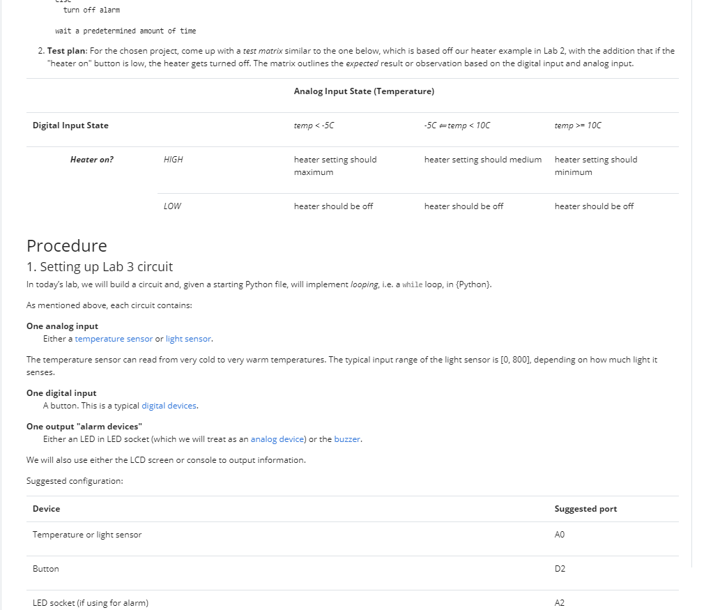
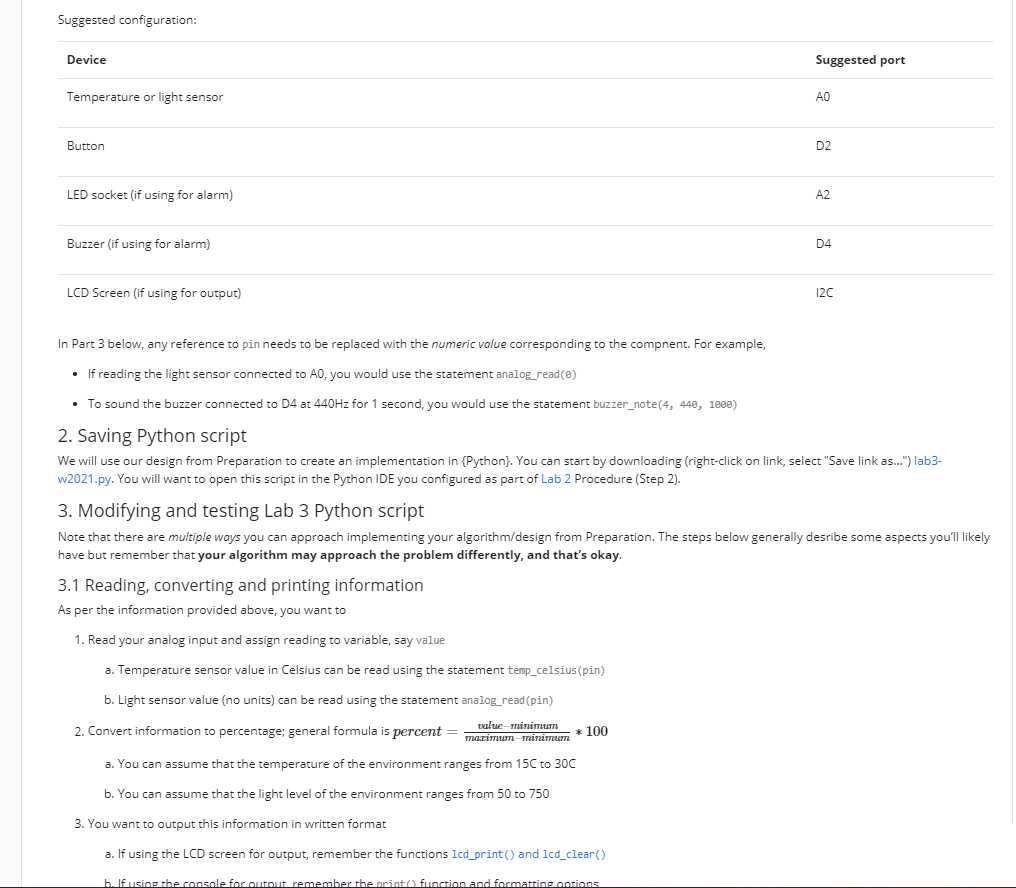
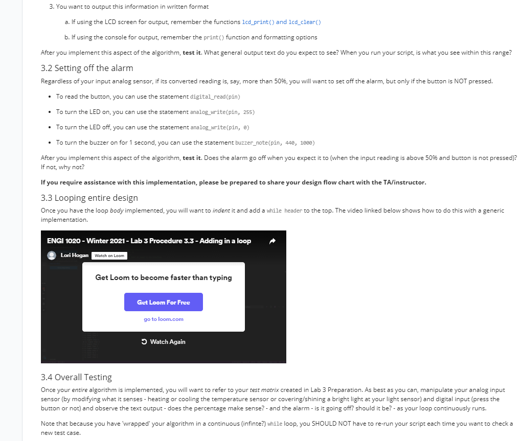
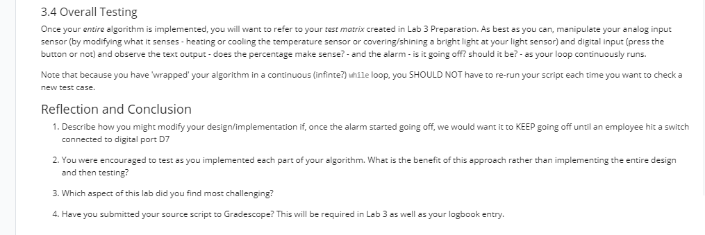
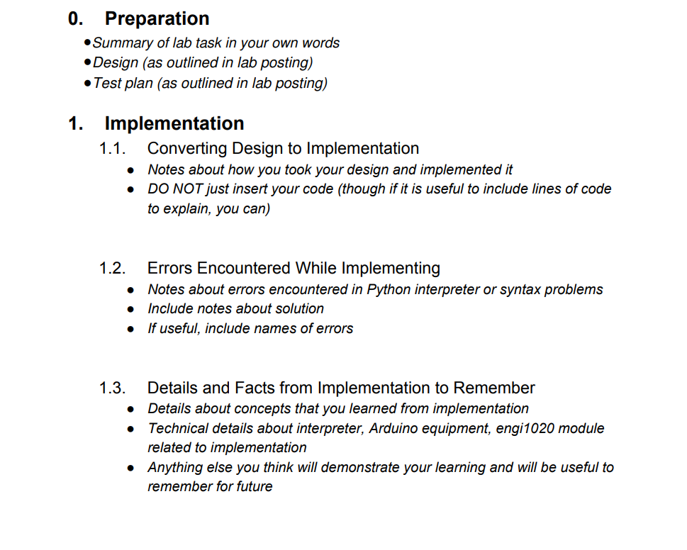
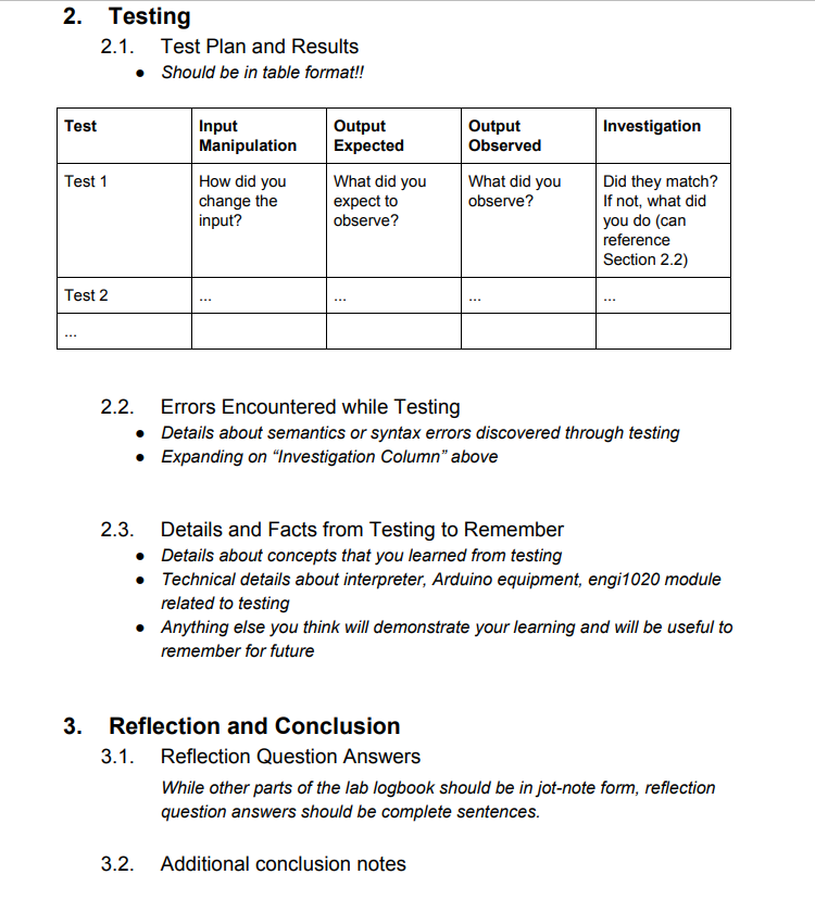
Purpose and Outcomes The scenario: You are creating an environmental monitoring system. When run, it will check an important environmental factor - either temperature OR light level - and output a "danger level" % (0 - 1009) to console or LCD screen at regular intervals. If personnel are not present indicated by whether or not the button is pressed) AND the temperature/light level is above a predefined threshold, the alarm will sound - either the buzzer will buzz OR the LED will turn on. In this lab, we will use two input devices and two output devices. Specifically, we will all use the same digital input source (the button) but choose one analog input source (the light sensor or temperature sensor). We can choose to use either the console (via print) or or LCD screen (via 'Icd_print(') but will choose either the buzzer or the LED to note alarm conditions. As in Lab 1, part of this lab will involve converting an input value (temperature or light level) to an output value (this time, a percentage level). The relationship between input reading and output percentage will be a linear relationship. Similar to Lab 2, we will use conditional flow control to manipulate our chosen output device (buzzer or LED) based on the value of the inputs. In all cases, we will: practice calling functions and implementing statements and expressions in Python; practice implementing conditional flow control through an IF statement; and practice implementing simple looping via the WHILE loop. By the end of this lab, you should be able to: describe the aspects and importance of looping vs conditional flow control in programming; and implement looping within a Python scrpit for a given problem. Preparation Record your pre-lab work as part of your logbook entry. 1. Design: Referencing lecture material if needed, draw a flow chart that represents a design for the problem that best fits the devices chosen for Lab 3. The problem can be summarized as: in a continuous loop: read the input analog device convert the input analog reading to an output percentage print output percentage if the digital input {button} is NOT pressed if the reading is above a given _threshold value manipulate alarm output device to show "alarm criteria" met else turn off alarm wait a predetermined amount of time 2 Tort nlan turn off alarm wait a predetermined amount of time 2. Test plan: For the chosen project, come up with a test matrix similar to the one below, which is based off our heater example in Lab 2, with the addition that if the "heater on" button is low, the heater gets turned off. The matrix outlines the expected result or observation based on the digital input and analog input. Analog Input State (Temperature) Digital Input State temp = 10C Heater on? HIGH heater setting should medium heater setting should maximum heater setting should minimum LOW heater should be off heater should be off heater should be off Procedure 1. Setting up Lab 3 circuit In today's lab, we will build a circuit and, given a starting Python file, will implement looping, i.e. a while loop, in {Python). As mentioned above, each circuit contains: One analog input Either a temperature sensor or light sensor. The temperature sensor can read from very cold to very warm temperatures. The typical input range of the light sensor is [0, 800), depending on how much light it senses. One digital input A button. This is a typical digital devices. One output "alarm devices" Either an LED in LED socket (which we will treat as an analog device) or the buzzer. We will also use either the LCD screen or console to output information. Suggested configuration: Device Suggested port Temperature or light sensor Button D2 LED socket (if using for alarm) A2 Suggested configuration: Device Suggested port Temperature or light sensor Button D2 LED socket (if using for alarm) A2 Buzzer (if using for alarm) D4 LCD Screen (if using for output) 120 In Part 3 below, any reference to pin needs to be replaced with the numeric value corresponding to the compnent. For example, If reading the light sensor connected to A0, you would use the statement analog_read() To sound the buzzer connected to D4 at 440Hz for 1 second, you would use the statement buzzer_note(4, 440, 1000) 2. Saving Python script We will use our des from Preparation to create an implementation in {Python). You can start by downloading (right-click on link, select "Save link as...") lab3- w2021.py. You will want to open this script in the Python IDE you configured as part of Lab 2 Procedure (Step 2). 3. Modifying and testing Lab 3 Python script Note that there are multiple ways you can approach implementing your algorithm/design from Preparation. The steps below generally desribe some aspects you'll likely have but remember that your algorithm may approach the problem differently, and that's okay. 3.1 Reading, converting and printing information As per the information provided above, you want to 1. Read your analog input and assign reading to variable, say value a. Temperature sensor value in Celsius can be read using the statement temp_celsius (pin) b. Light sensor value (no units) can be read using the statement analog_read(pin) value minimum 2. Convert information to percentage; general formula is percent mazimum minimum * 100 a. You can assume that the temperature of the environment ranges from 150 to 30C b. You can assume that the light level of the environment ranges from 50 to 750 3. You want to output this information in written format a. If using the LCD screen for output, remember the functions lcd_print() and lcd_clear() b. If using the console for autout remember the print function and formatrine antians 3.4 Overall Testing Once your entire algorithm is implemented, you will want to refer to your test matrix created in Lab 3 Preparation. As best as you can, manipulate your analog input sensor (by modifying what it senses - heating or cooling the temperature sensor or covering/shining a bright light at your light sensor) and digital input (press the button or not) and observe the text output - does the percentage make sense? - and the alarm - is it going off? should it be? - as your loop continuously runs. Note that because you have 'wrapped' your algorithm in a continuous (infinte?) while loop, you SHOULD NOT have to re-run your script each time you want to check a new test case. Reflection and Conclusion 1. Describe how you might modify your design/implementation if, once the alarm started going off, we would want it to KEEP going off until an employee hit a switch connected to digital port D7 2. You were encouraged to test as you implemented each part of your algorithm. What is the benefit of this approach rather than implementing the entire design and then testing? 3. Which aspect of this lab did you find most challenging? 4. Have you submitted your source script to Gradescope? This will be required in Lab 3 as well as your logbook entry. 0. Preparation Summary of lab task in your own words Design (as outlined in lab posting) Test plan (as outlined in lab posting) 1. Implementation 1.1. Converting Design to Implementation Notes about how you took your design and implemented it DO NOT just insert your code (though if it is useful to include lines of code to explain, you can) . . 1.2. Errors Encountered While Implementing Notes about errors encountered in Python interpreter or syntax problems Include notes about solution If useful, include names of errors 1.3. Details and Facts from Implementation to Remember Details about concepts that you learned from implementation Technical details about interpreter, Arduino equipment, engi 1020 module related to implementation Anything else you think will demonstrate your learning and will be useful to remember for future 2. Testing 2.1. Test Plan and Results Should be in table format!! Test Input Manipulation Output Expected Output Observed Investigation Test 1 What did you How did you change the input? What did you observe? expect to observe? Did they match? If not, what did you do (can reference Section 2.2) Test 2 2.2. Errors Encountered while Testing Details about semantics or syntax errors discovered through testing Expanding on Investigation Column" above 2.3. Details and Facts from Testing to Remember Details about concepts that you learned from testing Technical details about interpreter, Arduino equipment, engi1020 module related to testing Anything else you think will demonstrate your learning and will be useful to remember for future 3. Reflection and Conclusion 3.1. Reflection Question Answers While other parts of the lab logbook should be in jot-note form, reflection question answers should be complete sentences. 3.2. Additional conclusion notes Purpose and Outcomes The scenario: You are creating an environmental monitoring system. When run, it will check an important environmental factor - either temperature OR light level - and output a "danger level" % (0 - 1009) to console or LCD screen at regular intervals. If personnel are not present indicated by whether or not the button is pressed) AND the temperature/light level is above a predefined threshold, the alarm will sound - either the buzzer will buzz OR the LED will turn on. In this lab, we will use two input devices and two output devices. Specifically, we will all use the same digital input source (the button) but choose one analog input source (the light sensor or temperature sensor). We can choose to use either the console (via print) or or LCD screen (via 'Icd_print(') but will choose either the buzzer or the LED to note alarm conditions. As in Lab 1, part of this lab will involve converting an input value (temperature or light level) to an output value (this time, a percentage level). The relationship between input reading and output percentage will be a linear relationship. Similar to Lab 2, we will use conditional flow control to manipulate our chosen output device (buzzer or LED) based on the value of the inputs. In all cases, we will: practice calling functions and implementing statements and expressions in Python; practice implementing conditional flow control through an IF statement; and practice implementing simple looping via the WHILE loop. By the end of this lab, you should be able to: describe the aspects and importance of looping vs conditional flow control in programming; and implement looping within a Python scrpit for a given problem. Preparation Record your pre-lab work as part of your logbook entry. 1. Design: Referencing lecture material if needed, draw a flow chart that represents a design for the problem that best fits the devices chosen for Lab 3. The problem can be summarized as: in a continuous loop: read the input analog device convert the input analog reading to an output percentage print output percentage if the digital input {button} is NOT pressed if the reading is above a given _threshold value manipulate alarm output device to show "alarm criteria" met else turn off alarm wait a predetermined amount of time 2 Tort nlan turn off alarm wait a predetermined amount of time 2. Test plan: For the chosen project, come up with a test matrix similar to the one below, which is based off our heater example in Lab 2, with the addition that if the "heater on" button is low, the heater gets turned off. The matrix outlines the expected result or observation based on the digital input and analog input. Analog Input State (Temperature) Digital Input State temp = 10C Heater on? HIGH heater setting should medium heater setting should maximum heater setting should minimum LOW heater should be off heater should be off heater should be off Procedure 1. Setting up Lab 3 circuit In today's lab, we will build a circuit and, given a starting Python file, will implement looping, i.e. a while loop, in {Python). As mentioned above, each circuit contains: One analog input Either a temperature sensor or light sensor. The temperature sensor can read from very cold to very warm temperatures. The typical input range of the light sensor is [0, 800), depending on how much light it senses. One digital input A button. This is a typical digital devices. One output "alarm devices" Either an LED in LED socket (which we will treat as an analog device) or the buzzer. We will also use either the LCD screen or console to output information. Suggested configuration: Device Suggested port Temperature or light sensor Button D2 LED socket (if using for alarm) A2 Suggested configuration: Device Suggested port Temperature or light sensor Button D2 LED socket (if using for alarm) A2 Buzzer (if using for alarm) D4 LCD Screen (if using for output) 120 In Part 3 below, any reference to pin needs to be replaced with the numeric value corresponding to the compnent. For example, If reading the light sensor connected to A0, you would use the statement analog_read() To sound the buzzer connected to D4 at 440Hz for 1 second, you would use the statement buzzer_note(4, 440, 1000) 2. Saving Python script We will use our des from Preparation to create an implementation in {Python). You can start by downloading (right-click on link, select "Save link as...") lab3- w2021.py. You will want to open this script in the Python IDE you configured as part of Lab 2 Procedure (Step 2). 3. Modifying and testing Lab 3 Python script Note that there are multiple ways you can approach implementing your algorithm/design from Preparation. The steps below generally desribe some aspects you'll likely have but remember that your algorithm may approach the problem differently, and that's okay. 3.1 Reading, converting and printing information As per the information provided above, you want to 1. Read your analog input and assign reading to variable, say value a. Temperature sensor value in Celsius can be read using the statement temp_celsius (pin) b. Light sensor value (no units) can be read using the statement analog_read(pin) value minimum 2. Convert information to percentage; general formula is percent mazimum minimum * 100 a. You can assume that the temperature of the environment ranges from 150 to 30C b. You can assume that the light level of the environment ranges from 50 to 750 3. You want to output this information in written format a. If using the LCD screen for output, remember the functions lcd_print() and lcd_clear() b. If using the console for autout remember the print function and formatrine antians 3.4 Overall Testing Once your entire algorithm is implemented, you will want to refer to your test matrix created in Lab 3 Preparation. As best as you can, manipulate your analog input sensor (by modifying what it senses - heating or cooling the temperature sensor or covering/shining a bright light at your light sensor) and digital input (press the button or not) and observe the text output - does the percentage make sense? - and the alarm - is it going off? should it be? - as your loop continuously runs. Note that because you have 'wrapped' your algorithm in a continuous (infinte?) while loop, you SHOULD NOT have to re-run your script each time you want to check a new test case. Reflection and Conclusion 1. Describe how you might modify your design/implementation if, once the alarm started going off, we would want it to KEEP going off until an employee hit a switch connected to digital port D7 2. You were encouraged to test as you implemented each part of your algorithm. What is the benefit of this approach rather than implementing the entire design and then testing? 3. Which aspect of this lab did you find most challenging? 4. Have you submitted your source script to Gradescope? This will be required in Lab 3 as well as your logbook entry. 0. Preparation Summary of lab task in your own words Design (as outlined in lab posting) Test plan (as outlined in lab posting) 1. Implementation 1.1. Converting Design to Implementation Notes about how you took your design and implemented it DO NOT just insert your code (though if it is useful to include lines of code to explain, you can) . . 1.2. Errors Encountered While Implementing Notes about errors encountered in Python interpreter or syntax problems Include notes about solution If useful, include names of errors 1.3. Details and Facts from Implementation to Remember Details about concepts that you learned from implementation Technical details about interpreter, Arduino equipment, engi 1020 module related to implementation Anything else you think will demonstrate your learning and will be useful to remember for future 2. Testing 2.1. Test Plan and Results Should be in table format!! Test Input Manipulation Output Expected Output Observed Investigation Test 1 What did you How did you change the input? What did you observe? expect to observe? Did they match? If not, what did you do (can reference Section 2.2) Test 2 2.2. Errors Encountered while Testing Details about semantics or syntax errors discovered through testing Expanding on Investigation Column" above 2.3. Details and Facts from Testing to Remember Details about concepts that you learned from testing Technical details about interpreter, Arduino equipment, engi1020 module related to testing Anything else you think will demonstrate your learning and will be useful to remember for future 3. Reflection and Conclusion 3.1. Reflection Question Answers While other parts of the lab logbook should be in jot-note form, reflection question answers should be complete sentences. 3.2. Additional conclusion notes
Step by Step Solution
There are 3 Steps involved in it

Get step-by-step solutions from verified subject matter experts