

Question: This is the question that you need to answer, you need to design the filter based on the details in the question: ** The subject
This is the question that you need to answer, you need to design the filter based on the details in the question:
** The subject for this question is RF TECHNIQUE & MICROWAVE
This is the specifications that you need to use for designing the filter:
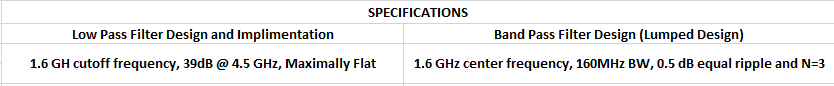
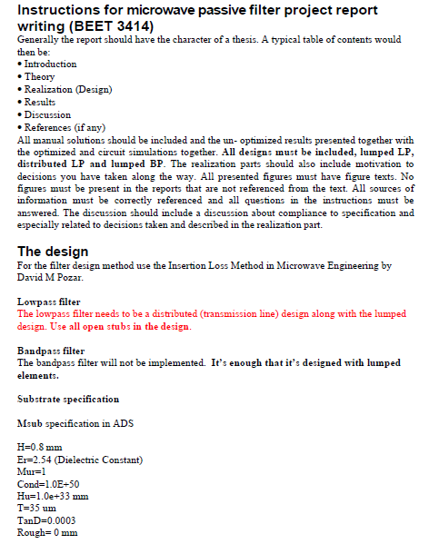
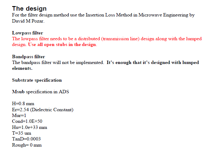
Instructions for microwave passive filter project report writing (BEET 3414) Generally the report should have the character of a thesis. A typical table of contents would then be: Introduction Theory Realization (Design) Results Discussion References (if any) All manual solutions should be included and the un- optimized results presented together with the optimized and circuit simulations together. All designs must be included, lumped LP, distributed LP and lumped BP. The realization parts should also include motivation to decisions you have taken along the way. All presented figures must have figure texts. No figures must be present in the reports that are not referenced from the text. All sources of information must be correctly referenced and all questions in the instructions must be answered. The discussion should include a discussion about compliance to specification and especially related to decisions taken and described in the realization part. The design For the filter design method use the Insertion Loss Method in Microwave Engineering by David M Pozar. Lowpass filter The lowpass filter needs to be a distributed (transmission line) design along with the lumped design. Use all open stubs in the design. Bandpass filter The bandpass filter will not be implemented. It's enough that it's designed with lumped elements. Substrate specification Msub specification in ADS H=0.8 mm Er=2.54 (Dielectric Constant) Mu=1 Cond=1.0E-50 Hu=1.0e+33 mm T=35 um TanD=0.0003 Rough=0 mm The design For the filter design method use the Insertion Loss Method in Microwave Engineering by David M Pozar. Lowpass filter The lowpass filter needs to be a distributed (transmission line) design along with the lumped design. Use all open stubs in the design. Bandpass filter The bandpass filter will not be implemented. It's enough that it's designed with lumped elements. Substrate specification Msub specification in ADS H=0.8 mm Er=2.54 (Dielectric Constant) Mur=1 Cond=1.0E+50 Hu=1.0e+33 mm T=35 um TanD=0.0003 Rough=0 mm SPECIFICATIONS Low Pass Filter Design and Implimentation Band Pass Filter Design (Lumped Design) 1.6 GH cutoff frequency, 39dB @ 4.5 GHz, Maximally Flat 1.6 GHz center frequency, 160MHz BW, 0.5 dB equal ripple and N=3 Instructions for microwave passive filter project report writing (BEET 3414) Generally the report should have the character of a thesis. A typical table of contents would then be: Introduction Theory Realization (Design) Results Discussion References (if any) All manual solutions should be included and the un- optimized results presented together with the optimized and circuit simulations together. All designs must be included, lumped LP, distributed LP and lumped BP. The realization parts should also include motivation to decisions you have taken along the way. All presented figures must have figure texts. No figures must be present in the reports that are not referenced from the text. All sources of information must be correctly referenced and all questions in the instructions must be answered. The discussion should include a discussion about compliance to specification and especially related to decisions taken and described in the realization part. The design For the filter design method use the Insertion Loss Method in Microwave Engineering by David M Pozar. Lowpass filter The lowpass filter needs to be a distributed (transmission line) design along with the lumped design. Use all open stubs in the design. Bandpass filter The bandpass filter will not be implemented. It's enough that it's designed with lumped elements. Substrate specification Msub specification in ADS H=0.8 mm Er=2.54 (Dielectric Constant) Mu=1 Cond=1.0E-50 Hu=1.0e+33 mm T=35 um TanD=0.0003 Rough=0 mm The design For the filter design method use the Insertion Loss Method in Microwave Engineering by David M Pozar. Lowpass filter The lowpass filter needs to be a distributed (transmission line) design along with the lumped design. Use all open stubs in the design. Bandpass filter The bandpass filter will not be implemented. It's enough that it's designed with lumped elements. Substrate specification Msub specification in ADS H=0.8 mm Er=2.54 (Dielectric Constant) Mur=1 Cond=1.0E+50 Hu=1.0e+33 mm T=35 um TanD=0.0003 Rough=0 mm SPECIFICATIONS Low Pass Filter Design and Implimentation Band Pass Filter Design (Lumped Design) 1.6 GH cutoff frequency, 39dB @ 4.5 GHz, Maximally Flat 1.6 GHz center frequency, 160MHz BW, 0.5 dB equal ripple and N=3
Step by Step Solution
There are 3 Steps involved in it

Get step-by-step solutions from verified subject matter experts