

Question: This question deals with multi-cycle processor implementation schemes. Consider a change to the multiple-cycle implementation that alters the register file so that it has only
This question deals with multi-cycle processor implementation schemes. Consider a change to the multiple-cycle implementation that alters the register file so that it has only one read port. Describe (via a diagram) any additional changes that will need to be made to the datapath in order to support this modification. Modify the finite state machine to indicate how the instructions will work, given your new datapath.
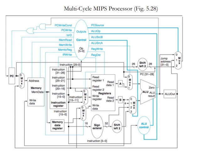
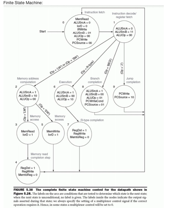
Multi-Cycle MIPS Processor (Fig. 5.28) PCWriteCond PCWrite PCSource ALUOP Outputs lord ALUSB Control ALUSCA MemRead Mem Write Memo Reg IRWrite Op 15-01 RegWrite Regst Jump address [31-01 KES Shift 28 26 left 2 2 PC PC [31-28 Address Zero Memory MemData Instruction (25-0] Instruction (31-26) Instruction [25-21) Instruction 120-16) Instruction [15-01 Instruction Instruction 115-11) register Instruction [15-01 Read register 1 Read Read data 1 register 2 Registers Write Read register data 2 Write data ALU ALU ALUOut result + Write data GNO NES 16 32 Memory data register Sign Shift left 2 ALU control extend Instruction 15-01 Finite State Machine: Instruction decodel register fetch Instruction fetch MemRead ALUSICA = 0 lorD0 IRWrite ALUSrcb-01 ALUOD = 00 PCWrite PCSource = 00 Start ALUSCA = 0 ALUSB = 11 ALUOp=00 (Op=R-type) (Op 'BEO) (Op = '') (Op = LW) or (Op = "SW) Execution Branch completion Jump completion Memory address computation 2 ALUSCA = 1 ALUSB = 10 ALUOD - 00 ALUSICA1 ALUSB - 00 ALUOp = 10 ALUSCA = 1 ALUSB-00 ALUOD 01 PC WriteCond PCSource = 01 PCWrite PCSource = 10 (Op = 'LW) (Op = 'SW) Memory access Memory access R-type completion MemRead ford = 1 MemWrite lord = 1 RegDst=1 RegWrite MemtoReg = 0 Memory read completon stop RegDst = 1 RegWrite MertoReg = 0 FIGURE 5.38 The complete finite state machine control for the datapath shown in Figure 5.28. The labels on the arcs are conditions that are tested to determine which state is the next state; when the next state is unconditional, no label is given. The labels inside the nodes indicate the output sig. nals asserted during that state; we always specify the setting of a multiplexor control signal if the correct operation requires it. Hence, in some states a multiplexor control will be set to 0
Step by Step Solution
There are 3 Steps involved in it

Get step-by-step solutions from verified subject matter experts