

Question: This submission requires you to develop, verify and validate a numerical model against both analytical and experimental data. This task will require you to
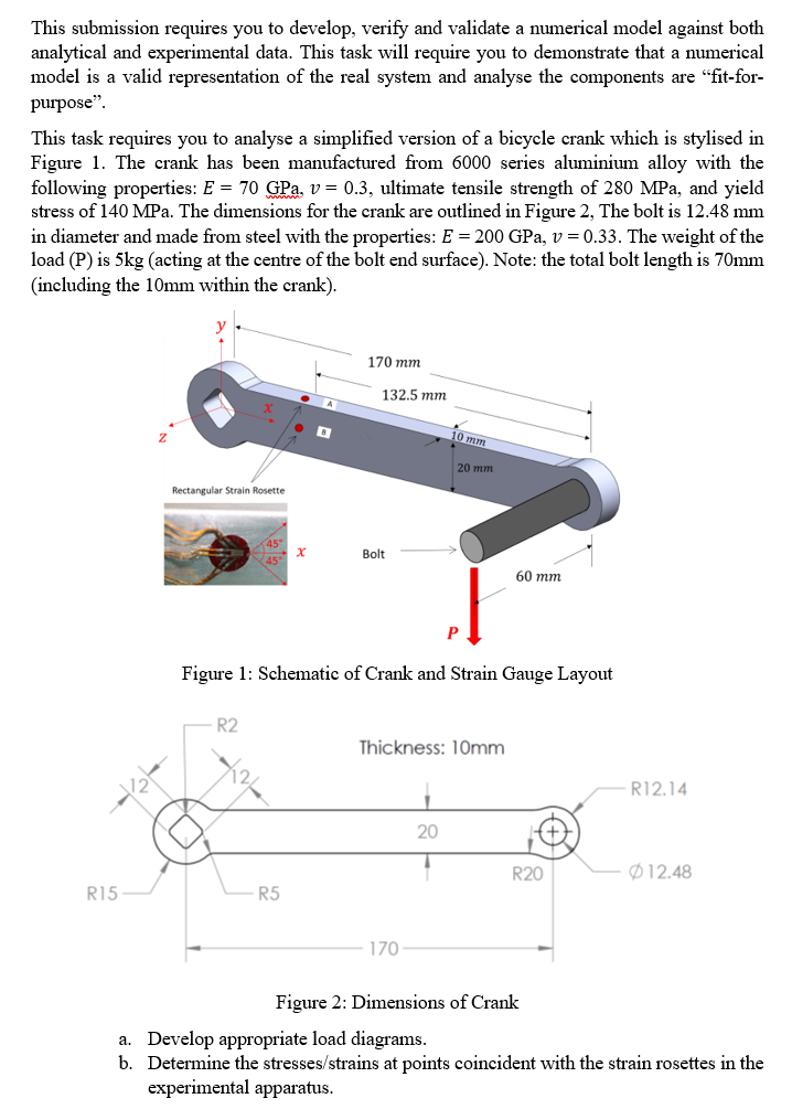
This submission requires you to develop, verify and validate a numerical model against both analytical and experimental data. This task will require you to demonstrate that a numerical model is a valid representation of the real system and analyse the components are "fit-for- purpose". This task requires you to analyse a simplified version of a bicycle crank which is stylised in Figure 1. The crank has been manufactured from 6000 series aluminium alloy with the following properties: E = 70 GPa, v = 0.3, ultimate tensile strength of 280 MPa, and yield stress of 140 MPa. The dimensions for the crank are outlined in Figure 2, The bolt is 12.48 mm in diameter and made from steel with the properties: E = 200 GPa, v = 0.33. The weight of the load (P) is 5kg (acting at the centre of the bolt end surface). Note: the total bolt length is 70mm (including the 10mm within the crank). Rectangular Strain Rosette 170 mm 132.5 mm mm 20 mm 45 x Bolt 45 60 mm Figure 1: Schematic of Crank and Strain Gauge Layout R2 R15 R5 Thickness: 10mm 170 20 R12.14 R20 12.48 Figure 2: Dimensions of Crank a. Develop appropriate load diagrams. b. Determine the stresses/strains at points coincident with the strain rosettes in the experimental apparatus.
Step by Step Solution
There are 3 Steps involved in it

Get step-by-step solutions from verified subject matter experts