

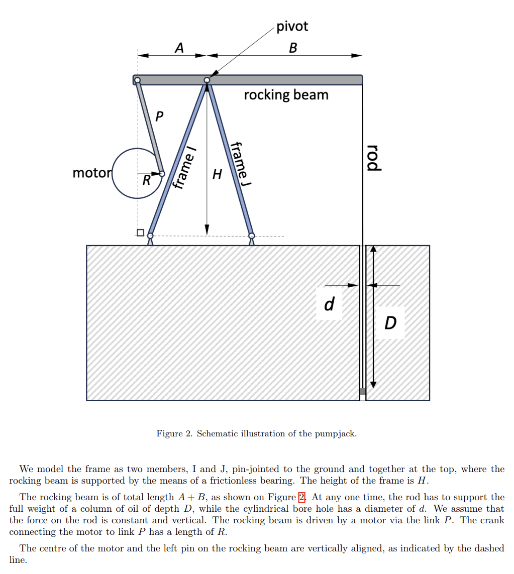
Question: This task is to optimize beam and frame of pumpjack shown in figure. The weight of crude oil is 2 6 . 8 kN .
This task is to optimize beam and frame of pumpjack shown in figure.
The weight of crude oil is kN
Dm dm Am Bm Pm Rm Hm
Considering the mechanism under operation as the motor rotates, determine the forces parallel and perpendicular to the beam. Calculate the resulting bending moments acting on the beam.
For a complete solution, consider different rotation angles of the motor.
The geometry of the pumpjack during operation is represented by the angles and as shown in Figure There is no need to determine the
geometry of the pumpjack at different angles, as angles corresponding to the operation of the pumpjack are tabulated in Table. Choose those which are indicative of the minimum and maximum bending moments in the beam. Justify your choices.
Ignore any inertial effects, ie throughout the rotation of the motor, consider each configuration in static equilibrium.
Design a beam made of uniform crosssection that deforms only elastically under operation. You may choose materials from those given in Table Aim to make the beam light and cheap. Justify your design decisions.
Express the stress distribution in the beam when radians and quantify the elastic energy stored in the beam. Depending on your beam design, you may need to apply simplifications or estimations.
Make sure to justify these in your discussion.
If the beam is overloaded, where will it most likely fail? Discuss the different stages of failure, including catastrophic failure. Illustrate the characteristics of the fracture.
B The frame
The aim of this section is to design the frame members I and J
The frame should be able to withstand the weight of the beam and the forces resulting from the operation of the pumpjack, including the weight of the crude oil and the forces due to the motor.
The frame members are made of mild steel. They may have different lengths but have the same profile and crosssectional area.
Derive an expression for the displacement of the pivot point ie where the bearing is as a function of the force at the bearing and the properties of the frame members I and J
Your expression should have the following parameters: lengths of I and J and ; angles of the members to the horizontal and ; the crosssection area ; the elastic modulus of mild steel.
Provide expressions for the axial forces along members I and J
In the following, use and The lengths of the
members I and J are and respectively. Given the axial forces, determine the uniform crosssectional area of the members such that they only deform compress or elongate within the elastic limit
Given the compressive axial forces along the members, calculate the second moment of area that is necessary to prevent buckling of the members. Suggest a suitable crosssectional profile made of thick steel plates.
You may decide to weld several of these together, in which case consider them as a single block of steel. You may find that you need to use a higher crosssection area to make sure the frame does not buckle under load.
Step by Step Solution
There are 3 Steps involved in it
1 Expert Approved Answer
Step: 1 Unlock

Question Has Been Solved by an Expert!
Get step-by-step solutions from verified subject matter experts
Step: 2 Unlock
Step: 3 Unlock