

Question: Three switches ( I 1 , I 2 , and I 3 ) control three output lamps ( O 1 , O 2 , and
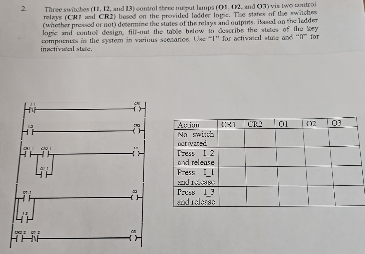
Three switches and control three output lamps O O and O via two control relays CR and CR based on the provided ladder logic. The states of the switches whether pressed or not determine the states of the relays and outputs. Based on the ladder logic and control design, fillout the table below to describe the states of the key compoenets in the system in various scenarios. Use for activated state and for inactivated state.
tableActionCRCROOOtableNo switchactivatedtablePress Iand releasetablePress Iand releasetablePress Iand release
Step by Step Solution
There are 3 Steps involved in it
1 Expert Approved Answer
Step: 1 Unlock

Question Has Been Solved by an Expert!
Get step-by-step solutions from verified subject matter experts
Step: 2 Unlock
Step: 3 Unlock