

Question: To set up a half - wave & full - wave rectifier circuits and to plot their input - output waveforms. Session Outcomes Explain the
To set up a halfwave & fullwave rectifier circuits and to plot their inputoutput waveforms.
Session Outcomes
Explain the basics of diodes, transistors, and optical devices.
ToolsSoftware
Procedural steps Tasks
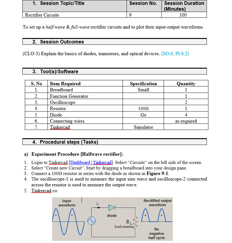
a Experiment Procedure Halfwave rectifier:
Login to Tinkercad Dashboard Tinkercad Select "Circuits" on the left side of the screen.
Select "Create new Circuit". Start by dragging a breadboard into your design pane.
Connect a Omega resistor in series with the diode as shown in Figure
The oscilloscope is used to measure the input sine wave and oscilloscope connected
across the resistor is used to measure the output wave.
Tinkercad co Input Output waveforms
Step by Step Solution
There are 3 Steps involved in it
1 Expert Approved Answer
Step: 1 Unlock

Question Has Been Solved by an Expert!
Get step-by-step solutions from verified subject matter experts
Step: 2 Unlock
Step: 3 Unlock