

Question: TOTAL HEAD, N . P . S . H . AND OTHER CALCULATION EXAMPLES Jacques Chaurette p . eng., www . lightmypump.com June 2 0
TOTAL HEAD, NPSH AND OTHER CALCULATION EXAMPLES
Jacques Chaurette p eng.,
wwwlightmypump.com
June
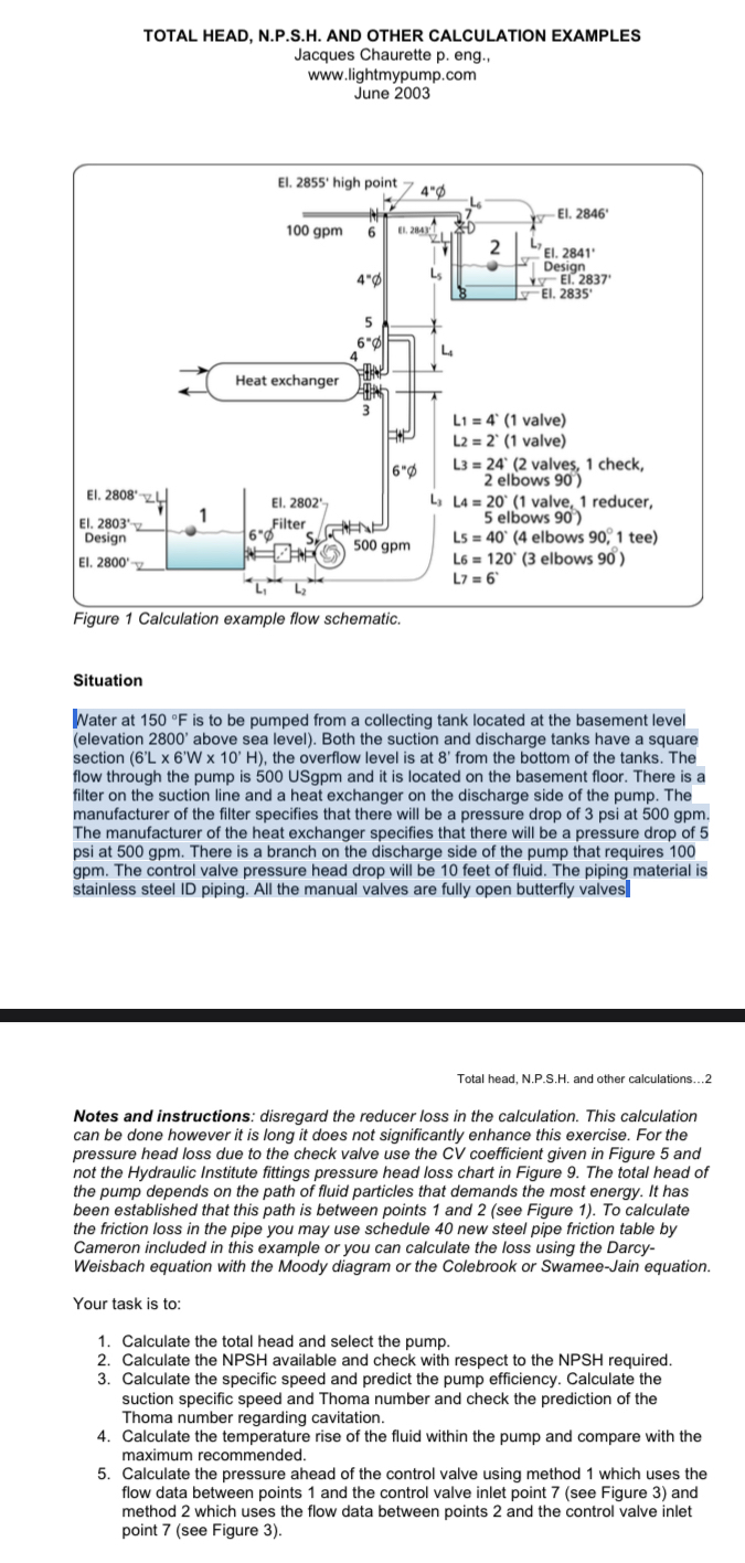
Figure Calculation example flow schematic.
Situation
Water at is to be pumped from a collecting tank located at the basement level elevation above sea level Both the suction and discharge tanks have a square section the overflow level is at from the bottom of the tanks. The flow through the pump is USgpm and it is located on the basement floor. There is a filter on the suction line and a heat exchanger on the discharge side of the pump. The manufacturer of the filter specifies that there will be a pressure drop of psi at The manufacturer of the heat exchanger specifies that there will be a pressure drop of at There is a branch on the discharge side of the pump that requires The control valve pressure head drop will be feet of fluid. The piping material is stainless steel ID piping. All the manual valves are fully open butterfly valves
Total head, NPSH and other calculations...
Notes and instructions: disregard the reducer loss in the calculation. This calculation can be done however it is long it does not significantly enhance this exercise. For the pressure head loss due to the check valve use the CV coefficient given in Figure and not the Hydraulic Institute fittings pressure head loss chart in Figure The total head of the pump depends on the path of fluid particles that demands the most energy. It has been established that this path is between points and see Figure To calculate the friction loss in the pipe you may use schedule new steel pipe friction table by Cameron included in this example or you can calculate the loss using the DarcyWeisbach equation with the Moody diagram or the Colebrook or SwameeJain equation.
Your task is to:
Calculate the total head and select the pump.
Calculate the NPSH available and check with respect to the NPSH required.
Calculate the specific speed and predict the pump efficiency. Calculate the suction specific speed and Thoma number and check the prediction of the Thoma number regarding cavitation.
Calculate the temperature rise of the fluid within the pump and compare with the maximum recommended.
Calculate the pressure ahead of the control valve using method which uses the flow data between points and the control valve inlet point see Figure and method which uses the flow data between points and the control valve inlet point see Figure
Step by Step Solution
There are 3 Steps involved in it
1 Expert Approved Answer
Step: 1 Unlock

Question Has Been Solved by an Expert!
Get step-by-step solutions from verified subject matter experts
Step: 2 Unlock
Step: 3 Unlock