

Question: Truss Analysis ( Group Project - 4 members / group max ) Final report ( one per group ) should only include: 1 - A
Truss Analysis Group Project membersgroup max
Final report one per group should only include:
A short introduction about your chosen design lines max
All sketches and CAD Drawings properly dimensioned
Detailed hand calculations and computer output forces in all members
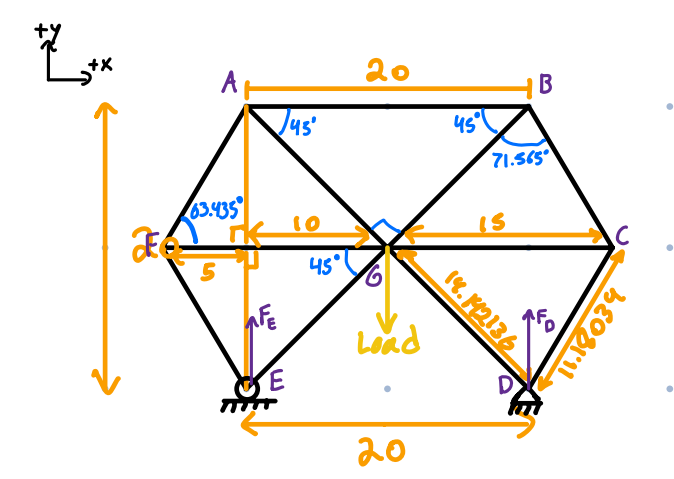
Task To analyse a truss
The truss should be in length in length and no more than in height. You are required to perform a detailed
structural analysis on the components of your trusses. You will also be required to model the truss to scale on D software
of your choice modeling software and supply detailed engineering drawings. A truss is a structure that consists of members
joined together at their endpoints. When designing and analyzing a truss structure that is to be subjected to a given load the
forces that each member and joint of the structure will undergo under the application of the load, must first be determined.
Each truss member acts as a twoforce member and therefore the forces at the ends of the member must be directed along
the axis of the member. If the force tends to pull away from the ends of the member it is a tensile force meaning it
undergoes tension. If the force tends to push into the member, it is compressive force C meaning it undergoescompression.
When analyzing the forces on the truss as an entire system the forces experienced by each individual member are considered
to be internal with respect to the entire system, therefore a separate method must be used to determine the forces applied to
each member.
Keep these couple basic assumptions in mind during the analysis:
All joints are pinned
All members are twoforce members
All loading is applied at the joints
Requirements
Your model should be exactly in length and no more than in height
Should have at least members
Should have equal support reactions when a weight is applied from one of the supports rollers or pins
Calculations of forces in all members and the reactions should be based on a load placed from one of the supports
Including zero force members is allowed as long as you are aware of the following:
They might make the truss shorter than long
They might make the number of members less than
Material used in the design is balsa wood square crosssection inch will not make a difference on the static analysis
Only one point load is to be applied
Load cannot not be applied at an angle vertical or horizontal only
Supports cannot be on inclined surface horizontal or vertical surfaces only
Members cannot overlap
Deliverables for ENGI
Report must include:
A short introduction
All hand sketches
Computer drawings properly dimensioned, no need for Multiview
Detailed analysis of the final design hand calculations and a table of the computer calculated forces
SolidWorks is the only D CAD Software permitted
Step by Step Solution
There are 3 Steps involved in it
1 Expert Approved Answer
Step: 1 Unlock

Question Has Been Solved by an Expert!
Get step-by-step solutions from verified subject matter experts
Step: 2 Unlock
Step: 3 Unlock