

Question: Use group 1 0 data A . Instructions This design project should be completed by groups. Each group is formed by 3 6 students. Each
Use group data A Instructions
This design project should be completed by groups. Each group is formed by students.
Each group should submit a project report and the spreadsheet calculations in Excel format. Full details of the design calculations method and analysis should be presented in the report in a logical manner.
Individual contribution to the reported should be clarified in the report.
Commercial simulation software cannot be used in the design.
Design Data
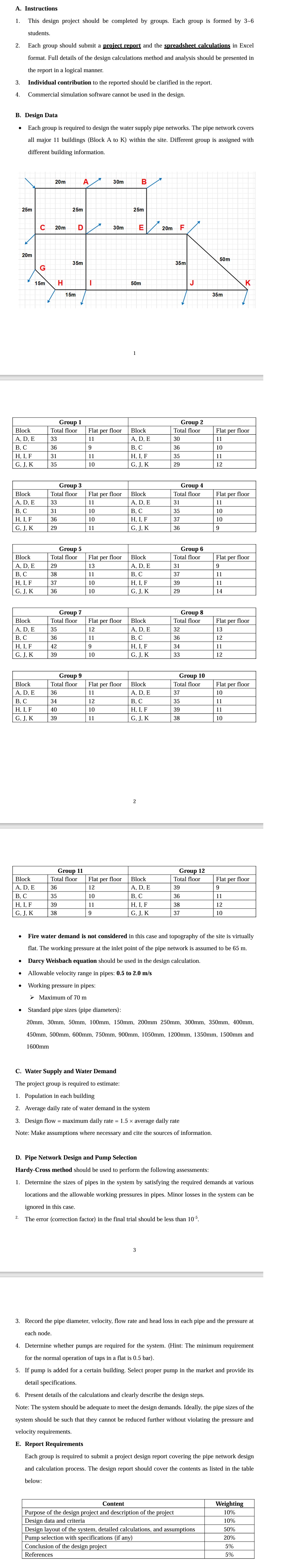
Each group is required to design the water supply pipe networks. The pipe network covers all major buildings Block A to K within the site. Different group is assigned with different building information.
tableGroup Group BlockTotal floor,Flat per floor,Block,Total floor,Flat per floorA EA D EB CB CH I, FH I, FG J KG J K
tableGroup Group BlockTotal floor,Flat per floor,Block,Total floor,Flat per floorA D EA D EB CB CH I, FH I, F J KG K
tableGroup Group BlockTotal floor,Flat per floor,Block,Total floor,Flat per floorA EA D EB CB CH I, FH I, FG J KG J K
tableGroup Group BlockTotal floor,Flat per floor,Block,Total floor,Flat per floorA D EA D EB CB CH I, FH I, FG J KG J K
tableGroup Group BlockTotal floor,Flat per floor,Block,Total floor,Flat per floorA D EA D EB CB CH I, F I, FG J KG K
Fire water demand is not considered in this case and topography of the site is virtually
flat. The working pressure at the inlet point of the pipe network is assumed to be
Darcy Weisbach equation should be used in the design calculation.
Allowable velocity range in pipes: to
Working pressure in pipes:
Standard pipe sizes pipe diameters
and
C Water Supply and Water Demand
The project group is required to estimate
Population in each building
Design flinty rate of water demand in the system
flow maximum daily rate average daily rate
D Pipe Network Design and Pump Selectio
HardyCross method should be used to perform the following assessments:
Determine the sizes of pipes in the system by satisfying the required demands at various
locations and the allowable working pressures in pipes. Minor losses in the system can b
ignored in this case.
The error correction factor in the final trial should be less than
Record the pipe diameter, velocity, flow rate and head loss in each pipe and the pressure at
each node.
Determine whether pumps are required for the system. Hint: The minimum requiremen
for the normal operation of taps in a flat is
If pump is added for a certain building. Select proper pump in the market and provide its
detail specifications.
Present details of the calculations and clearly describe the design steps.
Note: The system should be adequate to meet the design demands. Ideally, the pipe sizes of the
system should be such that they cannot be reduced further without violating the pressure and
E Report Requireme
Each group is required to submit a project design report covering the pipe network design
and calculation process. The design report should cover the contents as listed in the table
below:
tableContentWeightingPurpose of the design project and description of the project,Design data and criteria,Design layout of the system, detailed calculations, and assumptions,Pump selection with specifications if anyConclusion of the design project,References
Step by Step Solution
There are 3 Steps involved in it
1 Expert Approved Answer
Step: 1 Unlock

Question Has Been Solved by an Expert!
Get step-by-step solutions from verified subject matter experts
Step: 2 Unlock
Step: 3 Unlock