

Question: Use the data from the first two tables to complete the last table shown in Figure 5-4. 12 13 24 Figure 5-3 ATX 24-pin P1
Use the data from the first two tables to complete the last table
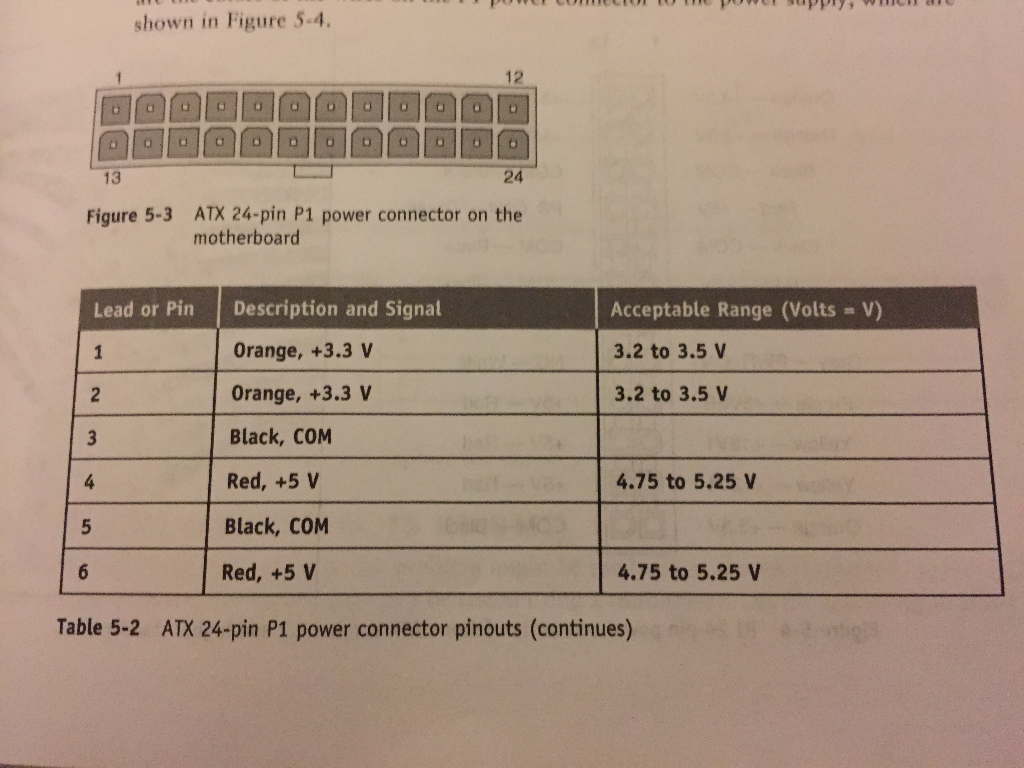
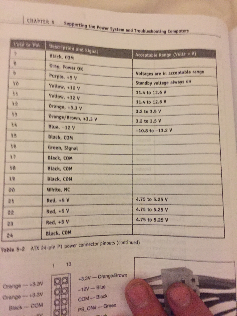
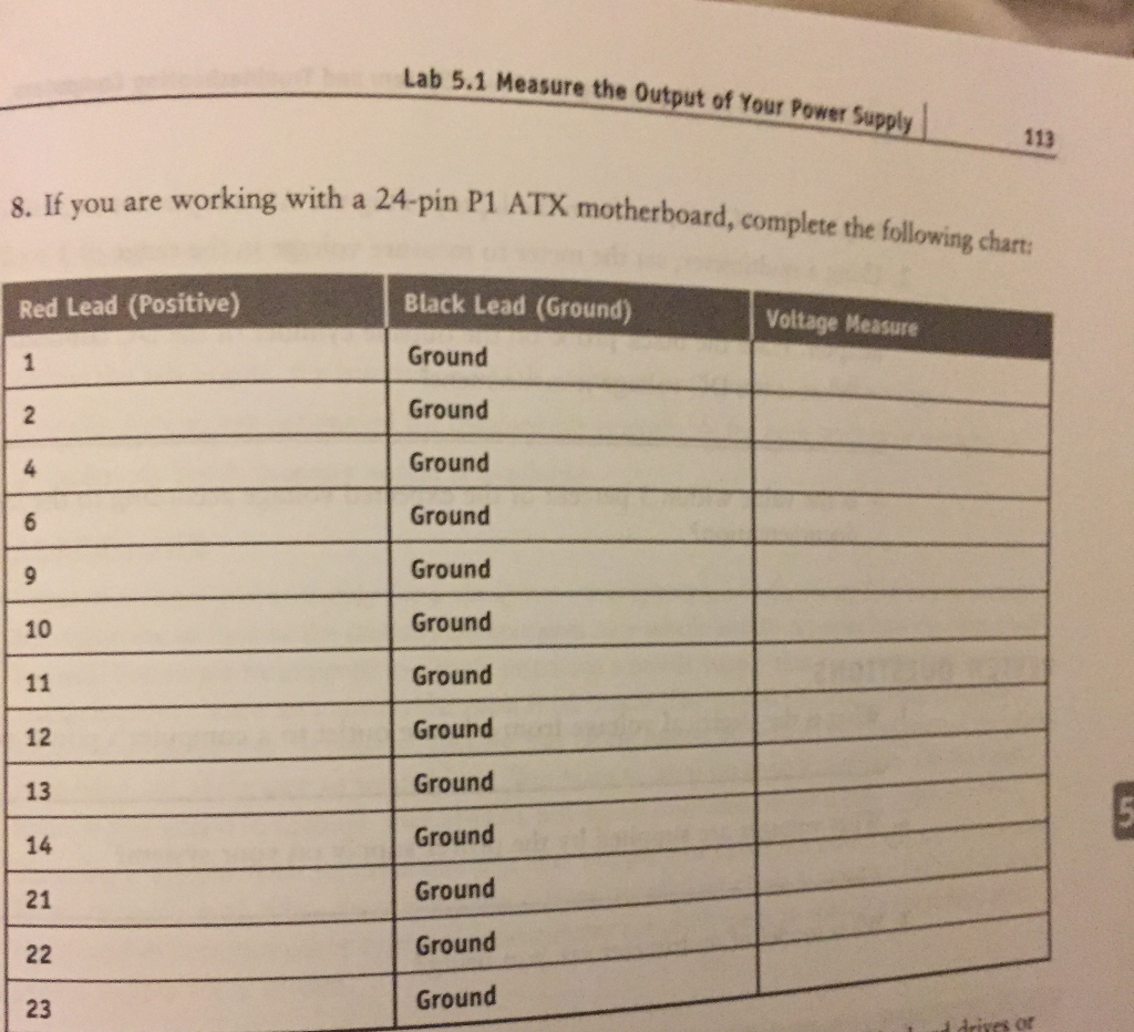
shown in Figure 5-4. 12 13 24 Figure 5-3 ATX 24-pin P1 power connector on the motherboard Acceptable Range (Volts V) 3.2 to 3.5 V 3.2 to 3.5 V Lead or Pin Description and Signal Orange, +3.3 V Orange, +3.3 V Black, COM Red, +5 V Black, COM Red, +5 V 4.75 to 5.25 V 4.75 to 5.25 V Table 5-2 ATX 24-pin P1 power connector pinouts (continues) EHAPTER Supporting the Power System and Troubleshooting Computer twad br Pm Desciption and Signal Acceptable Range (Volts- v) Black, COM Gray, Power OK Purple, +5 V Yellow, +12V Yellow, +12 V Orange, +3.3 V Orange/Brown, +3.3 V Blue, 12 V Black, coM Green, Signal Black, CONM Black, CONM Black, CONM White, NC Red, +5 V Red, +5 V Red, +5 V Voltages are in acceptable range Standby voltage always on 11.4 to 12.6 V 11.4 to 12.6 V 3.2 to 3.5v 3.2 to 3.5 V -10.8 to -13.2V to 15 18 18 20 4.75 to 5.25 V 4.75 to 5.25 V 4.75 to 5.25 V 21 23 24 Black, COM table 8-2 ATX 24-pin P1 power connector pinouts (continued) 1 13 Orange3.3v Orange w +3.3v Biack COM +3.3V-Orange/Brown -12VBlue COM-Black PSON#--Green 0011 Lab 5.1 Measure the Output of Your Power Suppl113 u are working with a 24-pin P1 ATX motherboard, complete the following charts 8. If you worki Black Lead (Ground) Ground Ground Ground Ground Ground Ground Ground Ground Ground Ground Ground Ground Ground Red Lead (Positive) Voltage Measure 10 12 13 14 21 23 of shown in Figure 5-4. 12 13 24 Figure 5-3 ATX 24-pin P1 power connector on the motherboard Acceptable Range (Volts V) 3.2 to 3.5 V 3.2 to 3.5 V Lead or Pin Description and Signal Orange, +3.3 V Orange, +3.3 V Black, COM Red, +5 V Black, COM Red, +5 V 4.75 to 5.25 V 4.75 to 5.25 V Table 5-2 ATX 24-pin P1 power connector pinouts (continues) EHAPTER Supporting the Power System and Troubleshooting Computer twad br Pm Desciption and Signal Acceptable Range (Volts- v) Black, COM Gray, Power OK Purple, +5 V Yellow, +12V Yellow, +12 V Orange, +3.3 V Orange/Brown, +3.3 V Blue, 12 V Black, coM Green, Signal Black, CONM Black, CONM Black, CONM White, NC Red, +5 V Red, +5 V Red, +5 V Voltages are in acceptable range Standby voltage always on 11.4 to 12.6 V 11.4 to 12.6 V 3.2 to 3.5v 3.2 to 3.5 V -10.8 to -13.2V to 15 18 18 20 4.75 to 5.25 V 4.75 to 5.25 V 4.75 to 5.25 V 21 23 24 Black, COM table 8-2 ATX 24-pin P1 power connector pinouts (continued) 1 13 Orange3.3v Orange w +3.3v Biack COM +3.3V-Orange/Brown -12VBlue COM-Black PSON#--Green 0011 Lab 5.1 Measure the Output of Your Power Suppl113 u are working with a 24-pin P1 ATX motherboard, complete the following charts 8. If you worki Black Lead (Ground) Ground Ground Ground Ground Ground Ground Ground Ground Ground Ground Ground Ground Ground Red Lead (Positive) Voltage Measure 10 12 13 14 21 23 of
Step by Step Solution
There are 3 Steps involved in it

Get step-by-step solutions from verified subject matter experts