

Question: use Verilog HDL In this project, you need to implement a BCD adder-subtractor circuit shown in Figure 1. You need to build the system components
use Verilog HDL
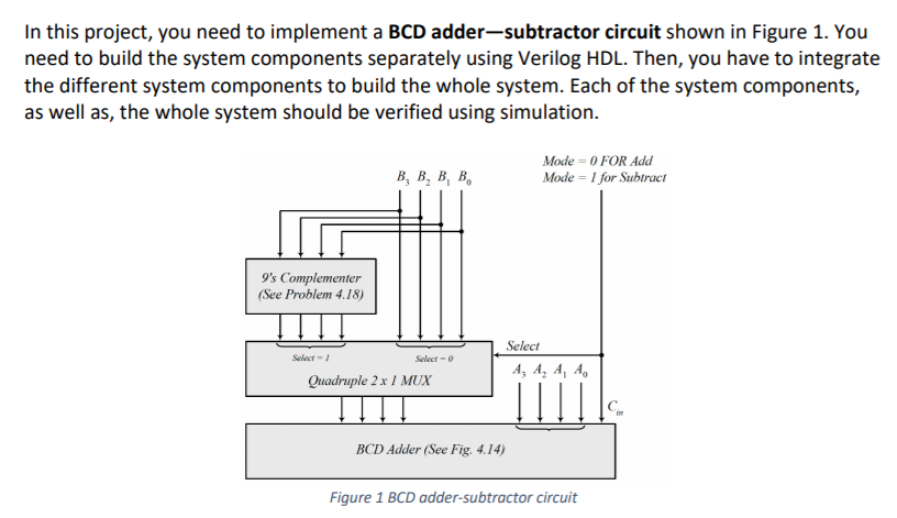
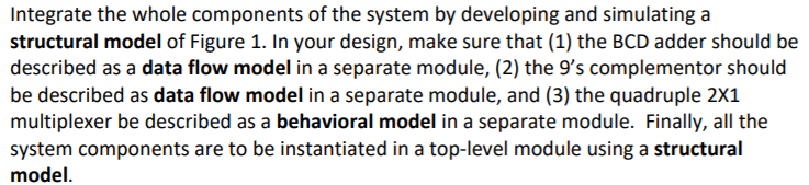
In this project, you need to implement a BCD adder-subtractor circuit shown in Figure 1. You need to build the system components separately using Verilog HDL. Then, you have to integrate the different system components to build the whole system. Each of the system components, as well as, the whole system should be verified using simulation. B, B, BB, Mode = 0 FOR Add Mode = 1 for Subtract 9's Complementer (See Problem 4.18) Select- Select- Select A A A A Quadruple 2 x / MUX BCD Adder (See Fig. 4.14) Figure 1 BCD adder-subtractor circuit Integrate the whole components of the system by developing and simulating a structural model of Figure 1. In your design, make sure that (1) the BCD adder should be described as a data flow model in a separate module, (2) the 9's complementor should be described as data flow model in a separate module, and (3) the quadruple 2X1 multiplexer be described as a behavioral model in a separate module. Finally, all the system components are to be instantiated in a top-level module using a structural model
Step by Step Solution
There are 3 Steps involved in it

Get step-by-step solutions from verified subject matter experts