Question: ****USING CISC 2017**** Question 2. (30 marks) Consider the 3-storey EBF shown in Fig. 1. The storey height is 3.8 m and the EBF height
****USING CISC 2017****
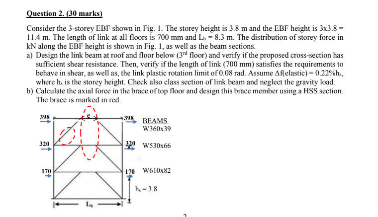
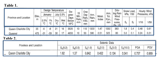
Question 2. (30 marks) Consider the 3-storey EBF shown in Fig. 1. The storey height is 3.8 m and the EBF height is 3x3.8 = 11.4 m. The length of link at all floors is 700 mm and Lb = 8.3 m. The distribution of storey force in kN along the EBF height is shown in Fig. 1, as well as the beam sections. a) Design the link beam at roof and floor below (3rd floor) and verify if the proposed cross-section has sufficient shear resistance. Then, verify if the length of link (700 mm) satisfies the requirements to behave in shear, as well as, the link plastic rotation limit of 0.08 rad. Assume Af(elastic) = 0.22%hs, where hs is the storey height. Check also class section of link beam and neglect the gravity load. b) Calculate the axial force in the brace of top floor and design this brace member using a HSS section. The brace is marked in red. 398 398 KA BEAMS W360x39 320 320 W530x66 170 170 W610x82 hs = 3.8 Table 1. Design Temperature De- 15 One January July 2.5% gree Elev. Min. Day Ann. Province and Location Days Rain, Rain, m 2.5% 1% Dry Wet Below Rain, 1/50 mm "C "C C "C mm 18C mm Queen Charlotte City 35 -6 8 21 16 3520 13 110 1300 Quesnel 475 31 33 30 17 4650 10 50 380 Table 2. Province and Location S.0.2) S.(0.5) S.(1.0) Queen Charlotte City 1.62 1.37 0.842 Driv Snow Load, Hourly Wind Anning Rain Pa, 1/50 Pressures, kPa Moist. Tot Wind Index Pp. Pres. mm sures, S S 1/10 1/50 P215 1.47 1350 360 1.8 0.4 0.48 0.61 0.51 525 80 3.0 0.1 0.24 0.31 o Seismic Data S.(2.0) S. (5.0) S (10.0) 0.452 0.124 0.041 PGA 0.757 PGV 0.989 Question 2. (30 marks) Consider the 3-storey EBF shown in Fig. 1. The storey height is 3.8 m and the EBF height is 3x3.8 = 11.4 m. The length of link at all floors is 700 mm and Lb = 8.3 m. The distribution of storey force in kN along the EBF height is shown in Fig. 1, as well as the beam sections. a) Design the link beam at roof and floor below (3rd floor) and verify if the proposed cross-section has sufficient shear resistance. Then, verify if the length of link (700 mm) satisfies the requirements to behave in shear, as well as, the link plastic rotation limit of 0.08 rad. Assume Af(elastic) = 0.22%hs, where hs is the storey height. Check also class section of link beam and neglect the gravity load. b) Calculate the axial force in the brace of top floor and design this brace member using a HSS section. The brace is marked in red. 398 398 KA BEAMS W360x39 320 320 W530x66 170 170 W610x82 hs = 3.8 Table 1. Design Temperature De- 15 One January July 2.5% gree Elev. Min. Day Ann. Province and Location Days Rain, Rain, m 2.5% 1% Dry Wet Below Rain, 1/50 mm "C "C C "C mm 18C mm Queen Charlotte City 35 -6 8 21 16 3520 13 110 1300 Quesnel 475 31 33 30 17 4650 10 50 380 Table 2. Province and Location S.0.2) S.(0.5) S.(1.0) Queen Charlotte City 1.62 1.37 0.842 Driv Snow Load, Hourly Wind Anning Rain Pa, 1/50 Pressures, kPa Moist. Tot Wind Index Pp. Pres. mm sures, S S 1/10 1/50 P215 1.47 1350 360 1.8 0.4 0.48 0.61 0.51 525 80 3.0 0.1 0.24 0.31 o Seismic Data S.(2.0) S. (5.0) S (10.0) 0.452 0.124 0.041 PGA 0.757 PGV 0.989


