

Question: USING MANUAL FINITE ELEMENT ANALYSIS ( stiffness and load matrices, boundary conditions, etc ) Q 1 . The beam shown in the figure below is
USING MANUAL FINITE ELEMENT ANALYSIS stiffness and load matrices, boundary conditions, etc
Q
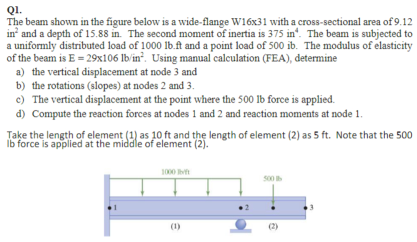
The beam shown in the figure below is a wideflange Wx with a crosssectional area of in and a depth of in The second moment of inertia is in The beam is subjected to a uniformly distributed load of lb ft and a point load of ib The modulus of elasticity of the beam is E xxlbin Using manual calculation FEA determine
a the vertical displacement at node and
b the rotations slopes at nodes and
c The vertical displacement at the point where the lb force is applied.
d Compute the reaction forces at nodes and and reaction moments at node Take the length of element as ft and the length of element as ft Note that the lb force is applied at the middle of element
Step by Step Solution
There are 3 Steps involved in it
1 Expert Approved Answer
Step: 1 Unlock

Question Has Been Solved by an Expert!
Get step-by-step solutions from verified subject matter experts
Step: 2 Unlock
Step: 3 Unlock