

Question: Using mcu frdm 64k 4. Develop an application that will simulate arming and disarming a security system by using two pushbuttons. The two pushbuttons will
Using mcu frdm 64k
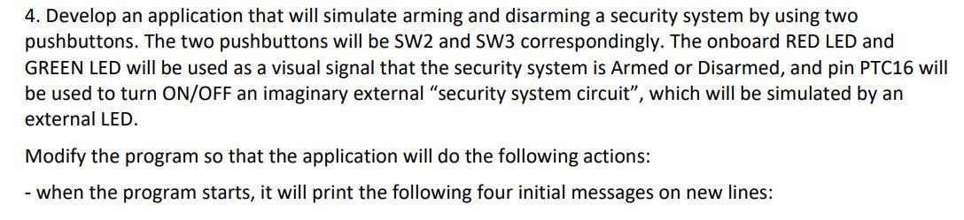
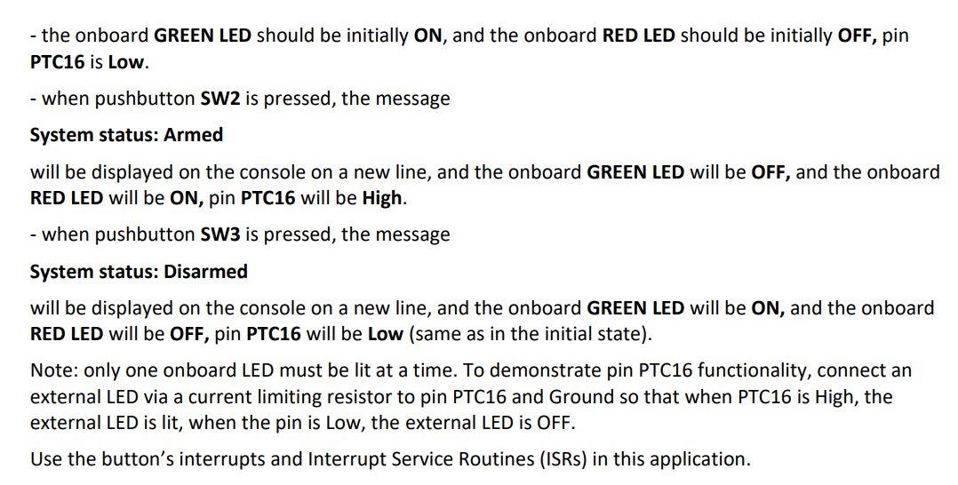
4. Develop an application that will simulate arming and disarming a security system by using two pushbuttons. The two pushbuttons will be SW2 and SW3 correspondingly. The onboard RED LED and GREEN LED will be used as a visual signal that the security system is Armed or Disarmed, and pin PTC16 will be used to turn ON/OFF an imaginary external "security system circuit", which will be simulated by an external LED. Modify the program so that the application will do the following actions: - when the program starts, it will print the following four initial messages on new lines: - the onboard GREEN LED should be initially ON, and the onboard RED LED should be initially OFF, pin PTC16 is Low. - when pushbutton SW2 is pressed, the message System status: Armed will be displayed on the console on a new line, and the onboard GREEN LED will be OFF, and the onboard RED LED will be ON, pin PTC16 will be High. - when pushbutton SW3 is pressed, the message System status: Disarmed will be displayed on the console on a new line, and the onboard GREEN LED will be ON, and the onboard RED LED will be OFF, pin PTC16 will be Low (same as in the initial state). Note: only one onboard LED must be lit at a time. To demonstrate pin PTC16 functionality, connect an external LED via a current limiting resistor to pin PTC16 and Ground so that when PTC16 is High, the external LED is lit, when the pin is Low, the external LED is OFF. Use the button's interrupts and Interrupt Service Routines (ISRs) in this application
Step by Step Solution
There are 3 Steps involved in it

Get step-by-step solutions from verified subject matter experts