

Question: Using the network diagram from Question #2 above, what would the virtual circuit tables look like after each of the following connections (Note that for
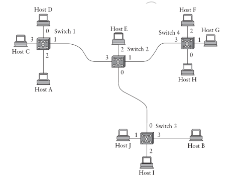
Using the network diagram from Question #2 above, what would the virtual circuit tables look like after each of the following connections (Note that for each connection you will want to share the resulting table for each of the four switches. Assume that the following connections are performed in sequential order without closing, and that the virtual circuit will always pick the lowest unused VCI on each link, starting with zero).
a) A connects to B
b) C connects to G
c) E connects to I
Step by Step Solution
There are 3 Steps involved in it
1 Expert Approved Answer
Step: 1 Unlock

Question Has Been Solved by an Expert!
Get step-by-step solutions from verified subject matter experts
Step: 2 Unlock
Step: 3 Unlock