

Question: Using the slope deflection method, determine the moments at the ends of each member of the frame shown in Figure Q4. The support at
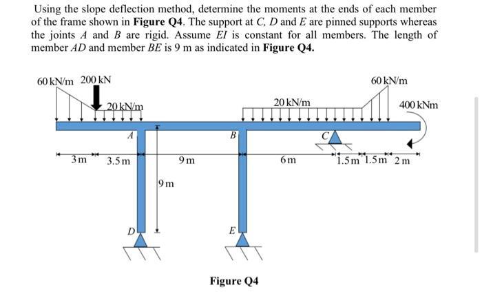
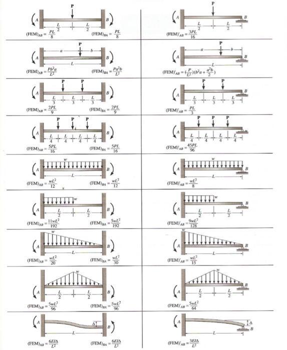
Using the slope deflection method, determine the moments at the ends of each member of the frame shown in Figure Q4. The support at C, D and E are pinned supports whereas the joints A and B are rigid. Assume El is constant for all members. The length of member AD and member BE is 9 m as indicated in Figure Q4. 60 kN/m 200 kN 3m 20 kN/m 3.5m D 9m 9m B E Figure Q4 20 kN/m 6m 60 kN/m 400 kNm 1.5m 1.5m 2m GE (FEM) GE (FEM) (FEM) (FEM)2PL 9 (FEM) (FEM) (FEM) (FEM) = (FEM) Pba SPL 16 wL 12 4+4+4+4 11 192 W wl. 20 Swl. 96 (FEM) A PL 6EJA V (FEM) +) (FEM)= (FEM) (FEM) (FEM) (FEM). (FEM) 2PL (FEM) SPL 16 w/2 Swl. 192 WL ") Swl? 96 6EIA D GE (FEM) (FEM/AB=(a+b) (PEMAR (FEM) (FEM) (FEM) (FEMA 3PL 16 (FEM) PL P 45PL 96 SwL (FEMIA 64 3EIA 2
Step by Step Solution
There are 3 Steps involved in it
Answer The following images are analysis results obtai... View full answer

Get step-by-step solutions from verified subject matter experts