

Question: VHDL Problem: Given: Assignment: Create a project named Miscellaneous which contains four files: (Hint: Concatenation operator & is very useful for this assignment) A. Add
VHDL Problem:
Given:
Assignment:
Create a project named Miscellaneous which contains four files: (Hint: Concatenation operator & is very useful for this assignment)
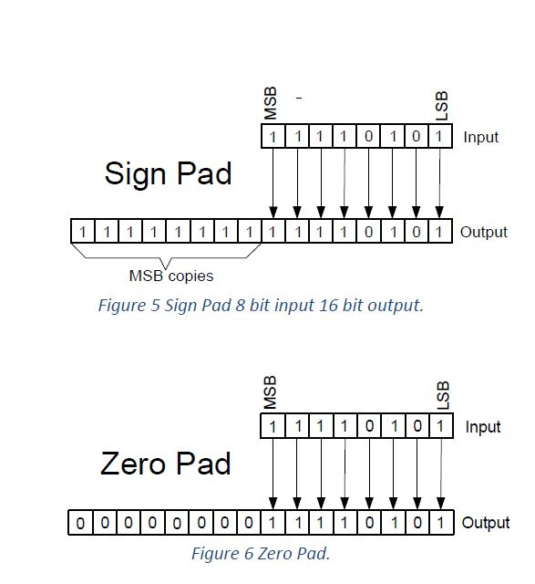
A. Add Incrementer.vhd file which contains a VHDL description of the Incrementer. B. Add Shifter.vhd file which contains a VHDL description of the shifter explained above. C. Add ZeroPad.vhd file which contains a VHDL description of a Zero pad circuit with an 8-bit input and a 32-bit output. D. Add SignPad.vhd file which contains a VHDL description of a Sign pad circuit with an 8-bit input and a 32-bit output.
Use the simulation features of Quartus to supply ALL your 4 components in the project with input values sufficiently diverse to demonstrate the correct operation of your design. (4 SIMULATIONS)
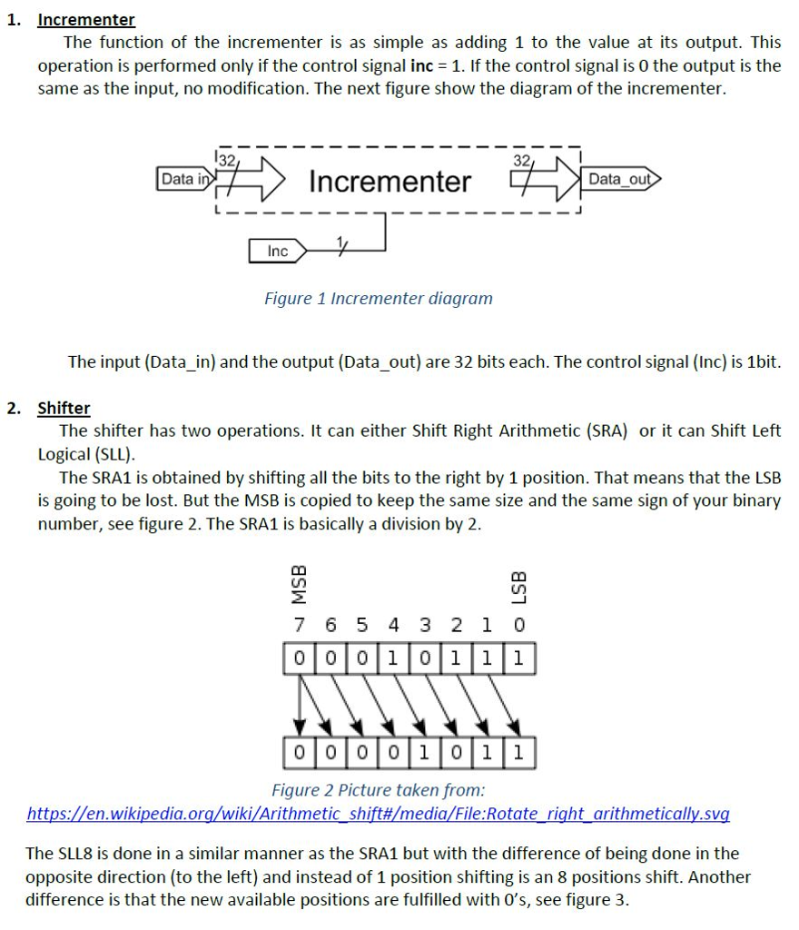
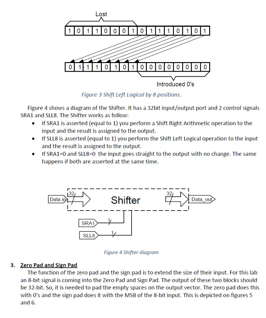
1. Incrementer The function of the incrementer is as simple as adding 1 to the value at its output. This operation is performed only if the control signal inc 1. If the control signal is 0 the output is the same as the input, no modification. The next figure show the diagram of the incrementer. 32 32 Data i Incrementer Data ou Inc Figure 1 Incrementer diagram The input (Data in) and the output (Data out) are 32 bits each. The control signal (Inc) is 1bit. 2. Shifter The shifter has two operations. It can either Shift Right Arithmetic (SRA) or it can Shift Left Logical (SLL) The SRA1 is obtained by shifting all the bits to the right by 1 position. That means that the LSB is going to be lost. But the MSB is copied to keep the same size and the same sign of your binary number, see figure 2. The SRA1 is basically a division by 2 7 6 5 4 3 2 1 0 000 1 0111 000 01 01 Figure 2 Picture taken from https://en.wikipedia.org/wiki/Arithmetic shift#/media File Rotate right arithmetically.Sg The SLL8 is done in a similar manner as the SRA1 but with the difference of being done in the opposite direction (to the left) and instead of 1 position shifting is an 8 positions shift. Another difference is that the new available positions are fulfilled with O's, see figure 3. 1. Incrementer The function of the incrementer is as simple as adding 1 to the value at its output. This operation is performed only if the control signal inc 1. If the control signal is 0 the output is the same as the input, no modification. The next figure show the diagram of the incrementer. 32 32 Data i Incrementer Data ou Inc Figure 1 Incrementer diagram The input (Data in) and the output (Data out) are 32 bits each. The control signal (Inc) is 1bit. 2. Shifter The shifter has two operations. It can either Shift Right Arithmetic (SRA) or it can Shift Left Logical (SLL) The SRA1 is obtained by shifting all the bits to the right by 1 position. That means that the LSB is going to be lost. But the MSB is copied to keep the same size and the same sign of your binary number, see figure 2. The SRA1 is basically a division by 2 7 6 5 4 3 2 1 0 000 1 0111 000 01 01 Figure 2 Picture taken from https://en.wikipedia.org/wiki/Arithmetic shift#/media File Rotate right arithmetically.Sg The SLL8 is done in a similar manner as the SRA1 but with the difference of being done in the opposite direction (to the left) and instead of 1 position shifting is an 8 positions shift. Another difference is that the new available positions are fulfilled with O's, see figure 3
Step by Step Solution
There are 3 Steps involved in it
To address the given VHDL problem with the corrections ... View full answer

Get step-by-step solutions from verified subject matter experts