

Question: We continue from the rectifier circuit in Fig. 1 . Given that V p = 2 3 0 2 V and the line angular frequency
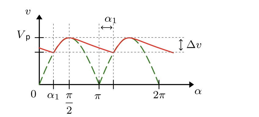
We continue from the rectifier circuit in Fig. Given that V p V and the line angular frequency The load resistor has the value R Fig. shows the output voltage waveform of the rectifier. The pulsating output of the diode rectification green is smoothen by a filtering capacitor at the output red The result is a DC voltage signal with a voltage ripple v V It is assumed that the capacitor value is large enough such that starting at the output voltage is supported by the discharging capacitor instead of the source AC voltage. The diodes are considered ideal diodes no forward voltage drop, no extra resistance, Figure : Output waveform of the diode rectifier. a Write the output voltage expression as a function of the phase angle using the given parameters. Use only the parameter names instead of substituting their actual values into the equations. Hint: C is discharging after b Find the value of c Find the value of the filtering capacitor such that the given voltage ripple condition is satisfied. d Calculate the load resistor average power consumption per source voltage period using the average power equation P T Z T vtit dt Z vi d TAU EEPEE Exercise e Calculate the average DC voltage level using the average signal equation V T Z T vt dt Z v d
Step by Step Solution
There are 3 Steps involved in it
1 Expert Approved Answer
Step: 1 Unlock

Question Has Been Solved by an Expert!
Get step-by-step solutions from verified subject matter experts
Step: 2 Unlock
Step: 3 Unlock