

Question: What is difference between clkT0(TIMER/COUNTER 0 ) and clkT2(TIMER/COUNTER 2). Using a Description and Reference below. 1) Description of TIMER/COUNTER 0. Timer/Counter Clock Sources The
What is difference between clkT0(TIMER/COUNTER 0 ) and clkT2(TIMER/COUNTER 2). Using a Description and Reference below.
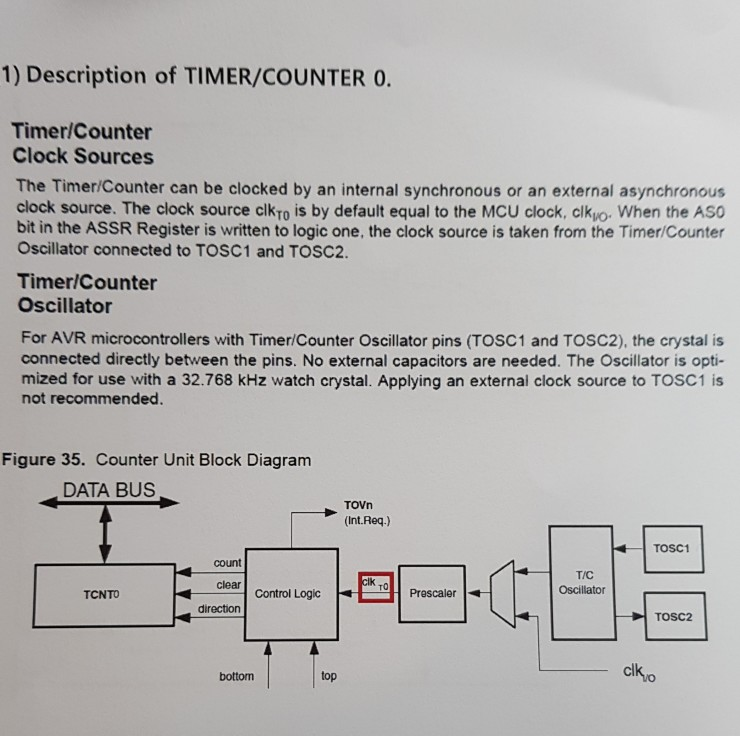
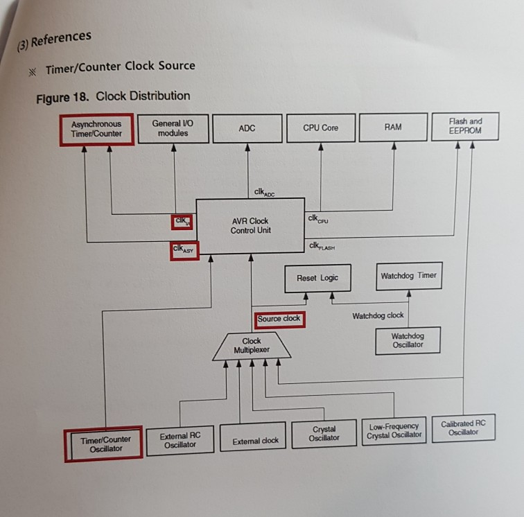
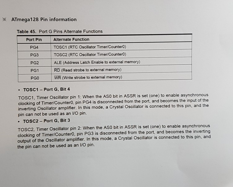
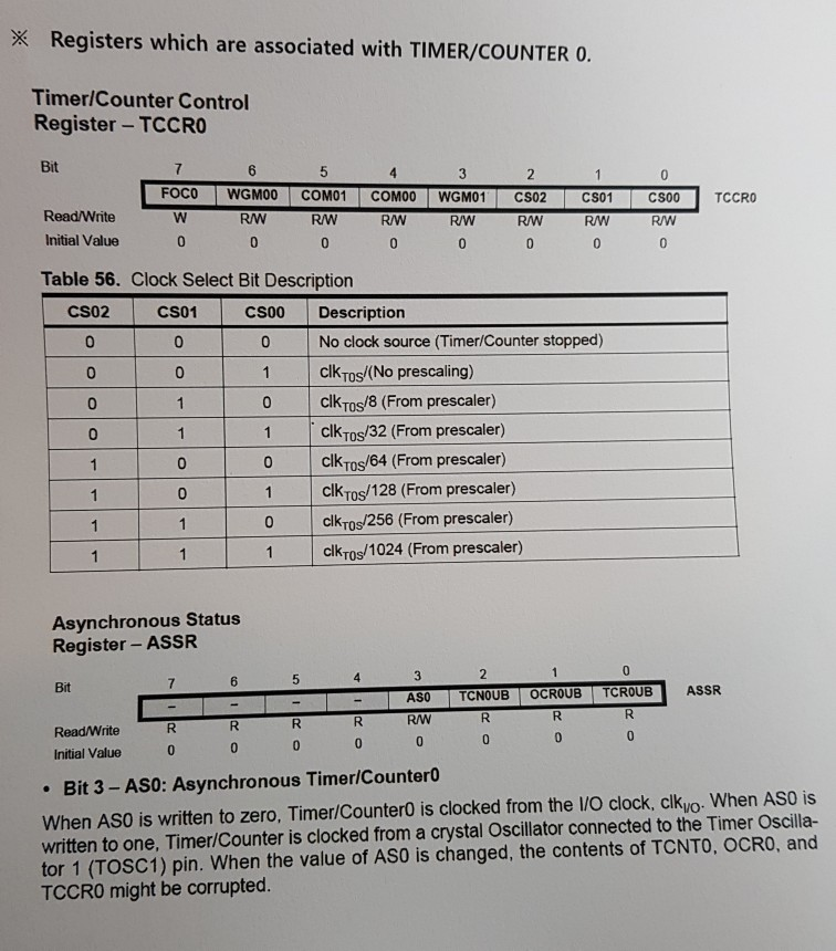
1) Description of TIMER/COUNTER 0. Timer/Counter Clock Sources The Timer/Counter can be clocked by an internal synchronous or an external asynchronous clock source. The clock source clkTo is by default equal to the MCU clock, clkuo When the ASO bit in the ASSR Register is written to logic one, the clock source is taken from the Timer/Counter Oscillator connected to TOSC1 and TOSC2. Timer/Counter Oscillator For AVR microcontrollers with Timer/Counter Oscillator pins (TOSC1 and TOSC2), the crystal is connected directly between the pins. No external capacitors are needed. The Oscillator is opti- mized for use with a 32.768 kHz watch crystal. Applying an external clock source to TOSC1 is not recommended. Figure 35. Counter Unit Block Diagram DATA BUS TOVn (Int.Req.) TOSC1 court T/C Oscillator lk clear control Logic TO TCNTO Prescaler direction top clko botton 1) Description of TIMER/COUNTER 0. Timer/Counter Clock Sources The Timer/Counter can be clocked by an internal synchronous or an external asynchronous clock source. The clock source clkTo is by default equal to the MCU clock, clkuo When the ASO bit in the ASSR Register is written to logic one, the clock source is taken from the Timer/Counter Oscillator connected to TOSC1 and TOSC2. Timer/Counter Oscillator For AVR microcontrollers with Timer/Counter Oscillator pins (TOSC1 and TOSC2), the crystal is connected directly between the pins. No external capacitors are needed. The Oscillator is opti- mized for use with a 32.768 kHz watch crystal. Applying an external clock source to TOSC1 is not recommended. Figure 35. Counter Unit Block Diagram DATA BUS TOVn (Int.Req.) TOSC1 court T/C Oscillator lk clear control Logic TO TCNTO Prescaler direction top clko botton
Step by Step Solution
There are 3 Steps involved in it

Get step-by-step solutions from verified subject matter experts