

Question: Modify Figure 11.10, the implementation of the SR master-slave flipflop, to provide asynchronous preset and clear inputs, as in Figure 11.32. When preset and
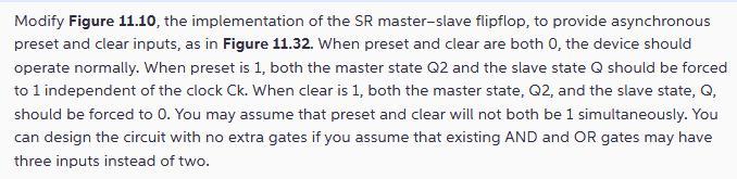
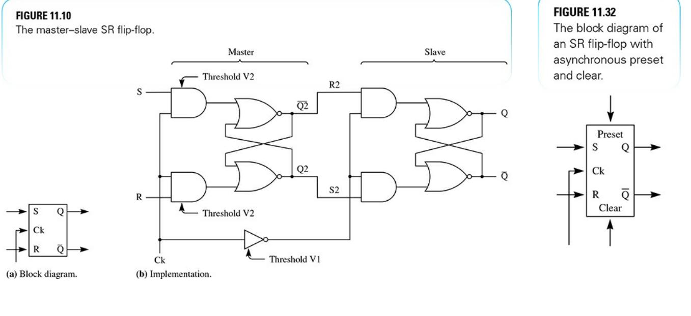
Modify Figure 11.10, the implementation of the SR master-slave flipflop, to provide asynchronous preset and clear inputs, as in Figure 11.32. When preset and clear are both 0, the device should operate normally. When preset is 1, both the master state Q2 and the slave state Q should be forced to 1 independent of the clock Ck. When clear is 1, both the master state, Q2, and the slave state, Q, should be forced to 0. You may assume that preset and clear will not both be 1 simultaneously. You can design the circuit with no extra gates if you assume that existing AND and OR gates may have three inputs instead of two. FIGURE 11.10 The master-slave SR flip-flop. Q HI Ck R Q (a) Block diagram. S R Ck Master Threshold V2 Threshold V2 (b) Implementation. Q2 Q2 Threshold VI R2 S2 Slave Q FIGURE 11.32 The block diagram of an SR flip-flop with asynchronous preset and clear. Preset S Q Ck R Q Clear
Step by Step Solution
3.48 Rating (155 Votes )
There are 3 Steps involved in it
To modify the implementation of the SR masterslave flipflop to provide asynchronous preset and clear ... View full answer

Get step-by-step solutions from verified subject matter experts