

Question: What to Do: Fill in the missing code in the two areas where it says Student provides missing component definitions and Student provides missing connection
What to Do: Fill in the missing code in the two areas where it says "Student provides missing component definitions" and
"Student provides missing connection definitions"
*****Take screenshot of compiled output which should look similar to the sample output shown below.*****
PROBLEM:
SDL.H located in this file
https://anotepad.comotes/cjympq
$-----------------------------------------------------------
$ Figure 3-3 (2-input version)
$ Figure3-3.sdl
$-----------------------------------------------------------
COMPONENTS
Student provides missing component definitions
ALIASES
A = IN#1
B = IN#2
M = OUT#1
CONNECTIONS
Student provides missing connection definitions
END
//----------------------------------------------------
// Figure 3-3 (2-input version)
// Figure3-3.cpp
//----------------------------------------------------
// Use default STATE strings " ON", "OFF", and "UNK"
#include ".SDLS.h"
//----------------------------------------------------
int main()
//----------------------------------------------------
{
/*
A B M
---- ---- ----
XXX XXX XXX
*/
try
{
CIRCUIT circuit;
circuit.Load("Figure3-3");
printf(" A B M ");
printf("---- ---- ---- ");
for (STATE A = OFF; A >= ON; A = Predecessor(A))
for (STATE IN2 = OFF; IN2 >= ON; IN2 = Predecessor(IN2))
{
circuit.SetIN("A",A);
// Two ways to set IN#2
circuit.SetIN(2,IN2);
circuit.SetIN("B",IN2);
circuit.SimulateLogic();
printf(" %3s %3s %3s ",
StateString(A),StateString(IN2),
StateString(circuit.GetOUT("M"))
// OR... StateString(circuit.GetOUT(1))
);
}
}
catch (SDLSEXCEPTION &exception)
{
printf("Exception: %s ",exception.GetErrorMessage());
}
system("PAUSE");
return( 0 );
}
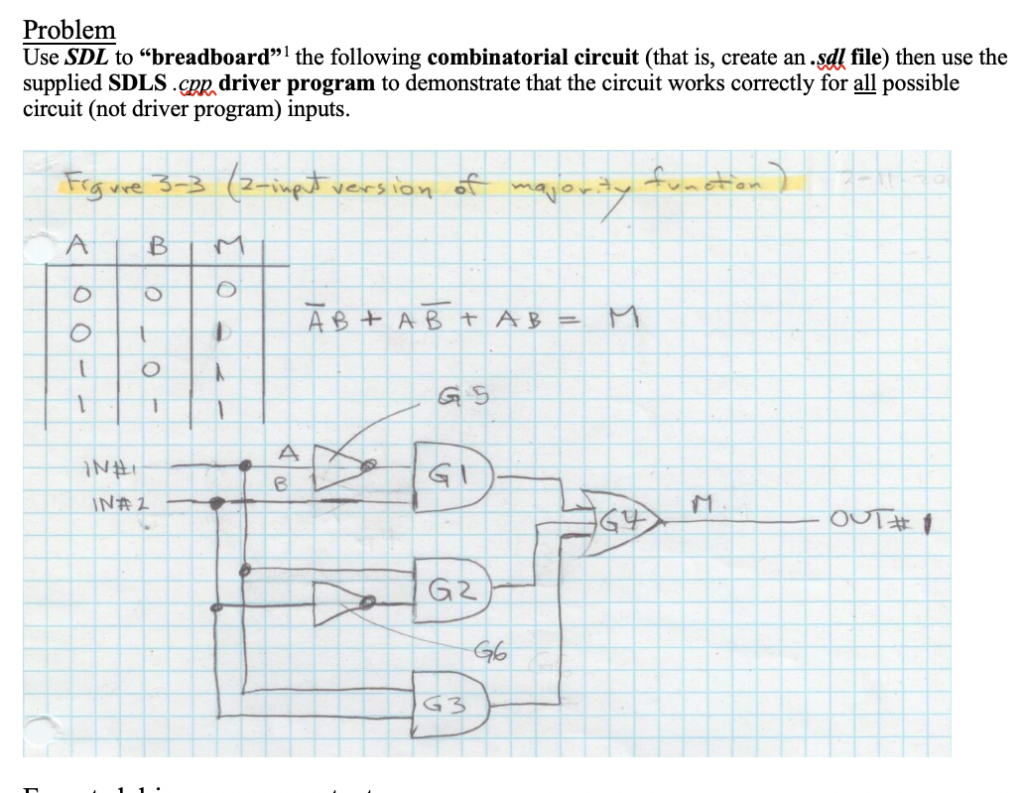
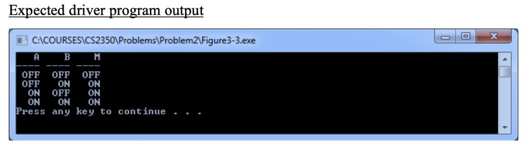
Problem Use SDL to "breadboard" the following combinatorial circuit (that is, create an.sdl file) then use the supplied SDLS .cR driver program to demonstrate that the circuit works correctly for all possible circuit (not driver program) inputs. a ve 2-ine version o A BIM G S t G 2 Expected driver program output CACOURSESCS2350Problems\Problem2Figure3-3.exe OFF OFF OFF OFF ON ON ON OFF ON ON ON ON Press any key to continue . Problem Use SDL to "breadboard" the following combinatorial circuit (that is, create an.sdl file) then use the supplied SDLS .cR driver program to demonstrate that the circuit works correctly for all possible circuit (not driver program) inputs. a ve 2-ine version o A BIM G S t G 2 Expected driver program output CACOURSESCS2350Problems\Problem2Figure3-3.exe OFF OFF OFF OFF ON ON ON OFF ON ON ON ON Press any key to continue
Step by Step Solution
There are 3 Steps involved in it

Get step-by-step solutions from verified subject matter experts