

Question: With the Control module implemented, the next task is to wire up the components of the processor and test the processor. Using SingleCycleProcTest.v, InstructionMemory.v and
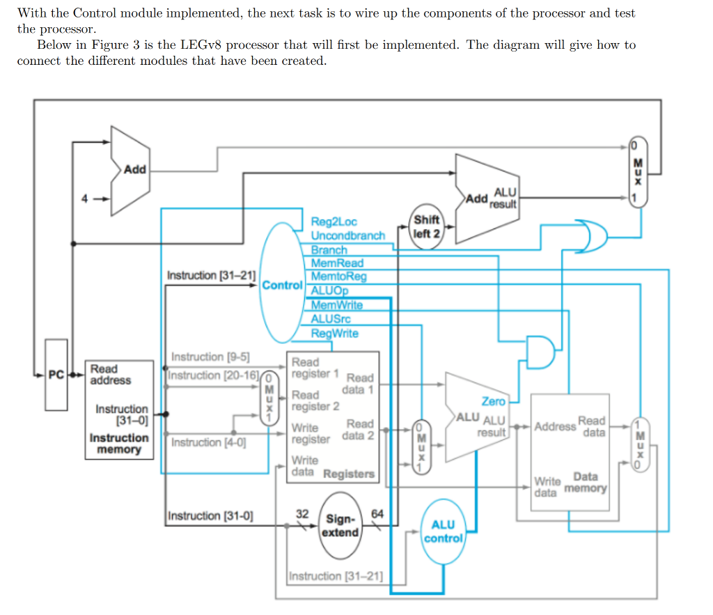
With the Control module implemented, the next task is to wire up the components of the processor and test the processor.
Using SingleCycleProcTest.v, InstructionMemory.v and DataMemory.v
----------------------------------------------------
`timescale 1ns / 1ps `define STRLEN 32 `define HalfClockPeriod 60 `define ClockPeriod `HalfClockPeriod * 2 module SingleCycleProcTest_v;
// These tasks are used to check if a given test has passed and // confirm that all tests passed. task passTest; input [63:0] actualOut, expectedOut; input [`STRLEN*8:0] testType; inout [7:0] passed; if(actualOut == expectedOut) begin $display ("%s passed", testType); passed = passed + 1; end else $display ("%s failed: 0x%x should be 0x%x", testType, actualOut, expectedOut); endtask task allPassed; input [7:0] passed; input [7:0] numTests; if(passed == numTests) $display ("All tests passed"); else $display("Some tests failed: %d of %d passed", passed, numTests); endtask // Inputs reg CLK; reg Reset_L; reg [63:0] startPC; reg [7:0] passed; reg [15:0] watchdog;
// Outputs wire [63:0] dMemOut; wire [63:0] currentPC; // Instantiate the Unit Under Test (UUT) SingleCycleProc uut ( .CLK(CLK), .Reset_L(Reset_L), .startPC(startPC), .currentPC(currentPC), .dMemOut(dMemOut) ); initial begin // Initialize Inputs Reset_L = 1; startPC = 0; passed = 0;
// Initialize Watchdog timer watchdog = 0; // Wait for global reset #(1 * `ClockPeriod); // Program 1 #1 Reset_L = 0; startPC = 0; #(1 * `ClockPeriod); Reset_L = 1;
// *********************************************************** // This while loop will continue cycling the processor until the // PC reaches the final instruction in the first test. If the // program forms an infinite loop, never reaching the end, the // watchdog timer will kick in and kill simulation after 64K // cycles. // ***********************************************************
while (currentPC
// *********************************************************** // Add your new tests here // ***********************************************************
// ...
// Done allPassed(passed, 1); // Be sure to change the one to match // the number of tests you add.
/* while(currentPC
$finish; end initial begin CLK = 0; end // The following is correct if clock starts at LOW level at StartTime // always begin #`HalfClockPeriod CLK = ~CLK; #`HalfClockPeriod CLK = ~CLK; watchdog = watchdog +1; end
// Kill the simulation if the watchdog hits 64K cycles always @* if (watchdog == 16'hFFFF) begin $display("Watchdog Timer Expired."); $finish; end endmodule
-----------------------------------------------------------
`timescale 1ns / 1ps `define SIZE 1024
module DataMemory(ReadData , Address , WriteData , MemoryRead , MemoryWrite , Clock); input [63:0] WriteData; input [63:0] Address; input Clock,MemoryRead,MemoryWrite; output reg [63:0] ReadData; reg [7:0] memBank[`SIZE-1:0];
// This task is used to write arbitrary data to the Data Memory by // the intialization block. task initset; input [63:0] addr; input [63:0] data; begin memBank[addr] = data[63:56] ; // Big-endian for the win... memBank[addr+1] = data[55:48]; memBank[addr+2] = data[47:40]; memBank[addr+3] = data[39:32]; memBank[addr+4] = data[31:24]; memBank[addr+5] = data[23:16]; memBank[addr+6] = data[15:8]; memBank[addr+7] = data[7:0]; end endtask initial begin // preseting some data in the data memory used by test #1
// Address 0x0 gets 0x1 initset( 64'h0, 64'h1); //Counter variable initset( 64'h8, 64'ha); //Part of mask initset( 64'h10, 64'h5); //Other part of mask initset( 64'h18, 64'h0ffbea7deadbeeff); //big constant initset( 64'h20, 64'h0); //clearing space
// Add any data you need for your tests here. end
// This always block reads the data memory and places a double word // on the ReadData bus. always @(posedge Clock) begin if(MemoryRead) begin ReadData[63:56]
// This always block takes data from the WriteData bus and writes // it into the DataMemory. always @(posedge Clock) begin if(MemoryWrite) begin memBank[Address]
--------------------------------------------------
this will be tied with
-------------------------
`timescale 1ns / 1ps
`define STRLEN 32
module SingleCycleControlTest;
task passTest;
input [63:0] actualOut, expectedOut;
input [`STRLEN*8:0] testType;
inout [7:0] passed;
if(actualOut == expectedOut) begin $display ("%s passed", testType); passed = passed + 1; end
else $display ("%s failed: %d should be %d", testType, actualOut, expectedOut);
endtask
task allPassed;
input [7:0] passed;
input [7:0] numTests;
if(passed == numTests) $display ("All tests passed");
else $display("Some tests failed");
endtask
// Inputs
reg [10:0] OpCode;
// Outputs
wire Reg2Loc, ALUSrc, MemToReg, RegWrite, MemRead, MemWrite, Branch, Uncondbranch;
wire [1:0] ALUOp;
reg [7:0] passed;
reg [7:0] numTests;
// Instantiate the Unit Under Test (UUT)
SingleCycleControl uut(
.Reg2Loc(Reg2Loc),
.ALUSrc(ALUSrc),
.MemToReg(MemToReg),
.RegWrite(RegWrite),
.MemRead(MemRead),
.MemWrite(MemWrite),
.Branch(Branch),
.Uncondbranch(Uncondbranch),
.ALUOp(ALUOp),
.Opcode(OpCode));
initial begin
// Initialize Inputs
OpCode = 11'b0000_0000_000;
passed = 7'b0;
numTests = 7'b0;
#3;
OpCode = 11'b11111000010; //LDUR Instruction
#3;
passTest({Uncondbranch, Branch, MemRead, MemToReg, MemWrite, ALUSrc, RegWrite, ALUOp},
{1'b0, 1'b0, 1'b1, 1'b1, 1'b0, 1'b1, 1'b1, 2'b00}, "LDUR Opcode", passed);
numTests = numTests + 1;
OpCode = 11'b11111000000; //STUR Instruction
#3;
passTest({Reg2Loc, Uncondbranch, Branch, MemRead, MemWrite, ALUSrc, RegWrite, ALUOp},
{1'b1, 1'b0, 1'b0, 1'b0, 1'b1, 1'b1, 1'b0, 2'b00}, "STUR Opcode", passed);
numTests = numTests + 1;
OpCode = 11'b10001011000; //ADD Instruction
#3;
passTest({Reg2Loc, Uncondbranch, Branch, MemRead, MemToReg, MemWrite, ALUSrc, RegWrite, ALUOp},
{1'b0, 1'b0, 1'b0, 1'b0, 1'b0, 1'b0, 1'b0, 1'b1, 2'b10}, "ADD Opcode", passed);
numTests = numTests + 1;
OpCode = 11'b11001011000; //SUB Instruction
#3;
passTest({Reg2Loc, Uncondbranch, Branch, MemRead, MemToReg, MemWrite, ALUSrc, RegWrite, ALUOp},
{1'b0, 1'b0, 1'b0, 1'b0, 1'b0, 1'b0, 1'b0, 1'b1, 2'b10}, "SUB Opcode", passed);
numTests = numTests + 1;
OpCode = 11'b10001010000; //AND Instruction
#3;
passTest({Reg2Loc, Uncondbranch, Branch, MemRead, MemToReg, MemWrite, ALUSrc, RegWrite, ALUOp},
{1'b0, 1'b0, 1'b0, 1'b0, 1'b0, 1'b0, 1'b0, 1'b1, 2'b10}, "AND Opcode", passed);
numTests = numTests + 1;
OpCode = 11'b10101010000; //ORR Instruction
#3;
passTest({Reg2Loc, Uncondbranch, Branch, MemRead, MemToReg, MemWrite, ALUSrc, RegWrite, ALUOp},
{1'b0, 1'b0, 1'b0, 1'b0, 1'b0, 1'b0, 1'b0, 1'b1, 2'b10}, "ORR Opcode", passed);
numTests = numTests + 1;
OpCode = 11'b10110100_010; //CBZ Instruction
#3;
passTest({Reg2Loc, Uncondbranch, Branch, MemRead, MemWrite, ALUSrc, RegWrite, ALUOp},
{1'b1, 1'b0, 1'b1, 1'b0, 1'b0, 1'b0, 1'b0, 2'b01}, "CBZ Opcode", passed);
numTests = numTests + 1;
OpCode = 11'b000101_00001; //B Instruction
#3;
passTest({Uncondbranch, MemRead, MemWrite, RegWrite},
{1'b1, 1'b0, 1'b0, 1'b0}, "B Opcode", passed);
numTests = numTests + 1;
allPassed(passed, numTests);
$finish;
end
endmodule
----------------------------------------
With the Control module implemented, the next task is to wire up the components of the processor and test the processor Below in Figure 3 is the LEGv8 processor that will first be implemented. The diagram will give how to connect the different modules that have been created MI Add ALU Add Shift Uncondbranch left 2 MemRead Instruction [31-21] Control MemtoR ALUSrc Write Instruction [9-5 Instruction [20-16 Read PCRead register 1 Read address Read data 1 Zero Instruction xregister 2 31-0 ALU ALU-Address data | Read Write Read register data 2 Write data Registers Instruction Instruction 14-0 memory Write Data data memory Instruction [31-0] 32 Sign 64 ALU control extend Instruction [31-21] With the Control module implemented, the next task is to wire up the components of the processor and test the processor Below in Figure 3 is the LEGv8 processor that will first be implemented. The diagram will give how to connect the different modules that have been created MI Add ALU Add Shift Uncondbranch left 2 MemRead Instruction [31-21] Control MemtoR ALUSrc Write Instruction [9-5 Instruction [20-16 Read PCRead register 1 Read address Read data 1 Zero Instruction xregister 2 31-0 ALU ALU-Address data | Read Write Read register data 2 Write data Registers Instruction Instruction 14-0 memory Write Data data memory Instruction [31-0] 32 Sign 64 ALU control extend Instruction [31-21]
Step by Step Solution
There are 3 Steps involved in it

Get step-by-step solutions from verified subject matter experts