

Question: 8. The produced part made from the drawing on the previous page is shown below, mated to the datum reference frame. Draw and shade
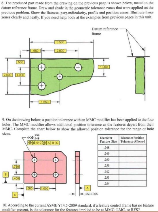
8. The produced part made from the drawing on the previous page is shown below, mated to the datum reference frame. Draw and shade in the geometric tolerance zones that were applied on the previous problem. Show the flatness, perpendieularity, profile and position zones. Illustrate these zones clearly and neatly. If you need help, look at the examples from previous pages in this unit. Datum reference frame 3.500 650 2.000 500 +) 1.000 2.000 1.000 | 1,650 - 9. On the drawing below, a position tolerance with an MMC modifier has been applied to the four holes. The MMC modifier allows additional position tolerance as the features depart from their MMC. Complete the chart below to show the allowed position tolerance for the range of hole sizes. 254 4x0 248 Diameter Diameter Position .010 AB C Feature Size Tolerance Allowed 248 249 250 750 251 252 400 253 254 500 1.000 250+005 10. According to the current ASME Y14.5-2009 standard, if a feature control frame has no feature modifier present, is the tolerance for the features implied to be at MMC, LMC, or RFS?
Step by Step Solution
3.35 Rating (155 Votes )
There are 3 Steps involved in it
To address the questions lets break them down and tackle each one separately Question 8 Task Draw and shade in the geometric tolerance zones that were ... View full answer

Get step-by-step solutions from verified subject matter experts