

Question: Write a code in VHDL that compiles in Quartus Prime and simulates in ModelSim.Please use all the original inputs and their symbols, create all files
Write a code in VHDL that compiles in Quartus Prime and simulates in ModelSim.Please use all the original inputs and their symbols, create all files and top entity too. Using VHDL and targeting the Altera DECV board, create a VHDL circuit for the timer system.
Your VHDL MUST adhere to the following guidelines:
a No integers types
b No latch warnings
c Hierarchical design and components for the delay unit, counter and display drivers.
In this lab, the concept of designing mechanism to keep track of time will be investigated. In a digital design, there are many applications that require a mechanism that is capable of tracking time. A timer andor counter is useful for a variety of tasks where a delay is required.
The technical objective of this lab will be met through the design and implementation of a presettable millisecond timer in VHDL
PreLaboratory:
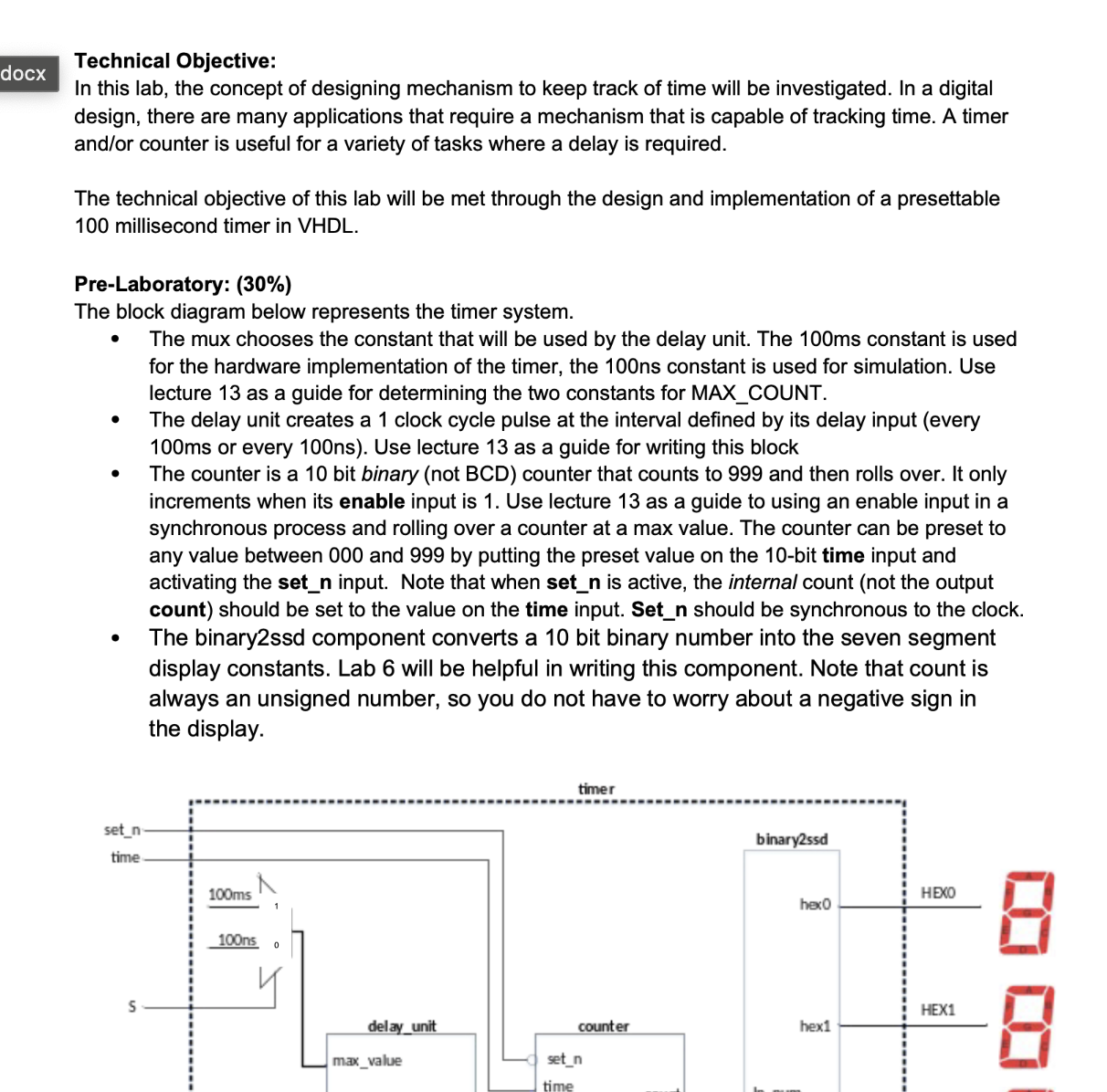
The block diagram below represents the timer system.
The mux chooses the constant that will be used by the delay unit. The ms constant is used for the hardware implementation of the timer, the ns constant is used for simulation. Use lecture as a guide for determining the two constants for MAXCOUNT.
The delay unit creates a clock cycle pulse at the interval defined by its delay input every ms or every ns Use lecture as a guide for writing this block
The counter is a bit binary not BCD counter that counts to and then rolls over. It only increments when its enable input is Use lecture as a guide to using an enable input in a synchronous process and rolling over a counter at a max value. The counter can be preset to any value between and by putting the preset value on the bit time input and activating the setn input. Note that when setn is active, the internal count not the output count should be set to the value on the time input. Setn should be synchronous to the clock.
The binaryssd component converts a bit binary number into the seven segment display constants. Lab will be helpful in writing this component. Note that count is always an unsigned number, so you do not have to worry about a negative sign in the display.
Step by Step Solution
There are 3 Steps involved in it
1 Expert Approved Answer
Step: 1 Unlock

Question Has Been Solved by an Expert!
Get step-by-step solutions from verified subject matter experts
Step: 2 Unlock
Step: 3 Unlock